Clarifier with Submerged Effluent Launder and Launder Sweeper System

Active Publication Date: 2021-10-28
OVIVO INC
View PDF0 Cites 0 Cited by
  • Summary
  • Abstract
  • Description
  • Claims
  • Application Information

AI Technical Summary

Benefits of technology

The invention is a solution for improving the quality of clarified liquid and preventing sludge from exiting with the clarified water. It involves a clarifier with a submerged effluent launder that has a sloped, submerged plate. A scum box is placed external to the clarifier to remove the scum and related piping and supports from inside the clarifier. The scum is swept into a low-profile scum trough and then flows out through a break in the clarifier wall to an external sludge discharge area. The sludge settles in the clarifier, as a second phase of settling. The clarifier effluent quality is improved, and algae growth is minimized or prevented. The patent text describes two embodiments of the invention, with the second embodiment avoiding interference with the scum box using a rake-attached, sweeping launder wiper.

Problems solved by technology

This can cause a problem of algae growth, and also, the solids settled onto the upper launder surface could potentially be removed, to allow a better clarifier effluent.
If a scum box or collection trough is located within the clarifier at a selected location adjacent to the scum surface, as is typical in clarifiers, no practical and efficient way to clean the sloped launder surface is available.
The scum collection trough or box and associated piping and supports will interfere.
These moving parts can become hung up on traditional scum box designs and can damage rake arms, cage and drive, which can be costly.

Method used


Image

  • Clarifier with Submerged Effluent Launder and Launder Sweeper System
  • Clarifier with Submerged Effluent Launder and Launder Sweeper System
  • Clarifier with Submerged Effluent Launder and Launder Sweeper System

Examples


Embodiment Construction

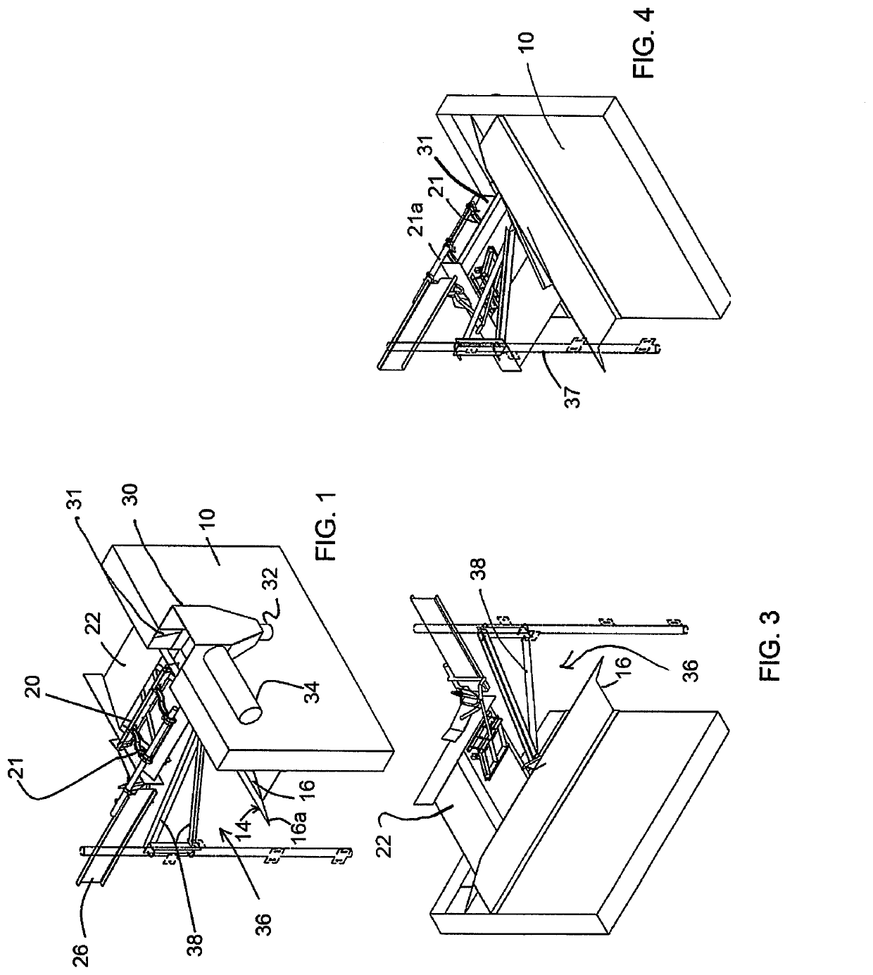
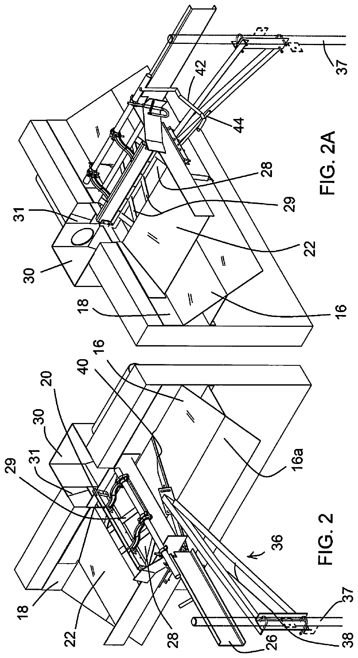
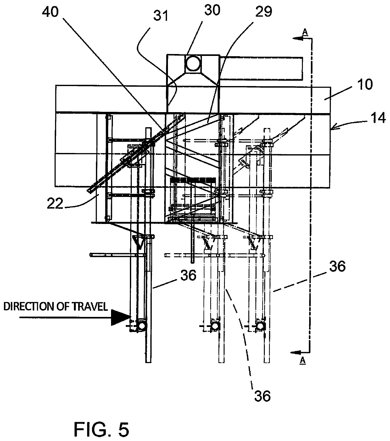
[0020]In the drawings, FIGS. 1-4 show the system of the invention, in connection with a wall 10 of a clarifier 12 (clarifier shown in FIG. 7). A small section of the wall 10 is seen in FIGS. 1-4.

[0021]A submerged effluent launder (SEL) is shown, as a fragmented section, at 14. This is essentially as in an embodiment of U.S. Pat. No. 9,919,244, a generally triangular cross-sectional shape with a sloped, submerged plate 16 which has submerged effluent holes (not shown) through which clarified liquid enters the launder for discharge from the clarifier.

[0022]A scum accumulating surface is at 18, a vertical surface at the top of the sloped plate 16, preferably an upper extension integral with the plate 16. The scum is wiped from the scum surface 18 by a skimmer or wiper blade 20 (essentially a squeegee) that has wipers on the end contacting the scum surface 18 as well as along its bottom. The end wiper brings scum to a flat, sloped trough shown at 22 that acts as a scum beach. When the s...


PUM

PropertyMeasurementUnit
Densityaaaaaaaaaa
Flexibilityaaaaaaaaaa
Circumferenceaaaaaaaaaa

Abstract

In a wastewater treatment system, a clarifier has a submerged effluent launder, with a sloped, submerged plate that allows clarified liquid to exit through submerged openings. The sloped surface tends to accumulate solids, which can lead to algae growth. Typical internal scum collection system equipment prevents any efficient way to clear the accumulated sludge off the launder surface because of interferences. As disclosed here, a scum discharge area or box is placed external to the clarifier in one embodiment. Scum is wiped from a vertical surface of the launder assembly, above the sloped launder surface, and swept over a scum beach at one position in the clarifier, to drop into a lower trough and the flow out through the clarifier wall to a drop out box or scum discharge area. This allows for a rake-attached, sweeping launder wiper to be moved with the clarifier's rake to remove the accumulation of sludge from the launder's submerged surface, without elaborate moving parts. The sludge is swept back to settle in the clarifier, improving effluent quality by preventing sludge from exiting along with clarified water. In another embodiment the scum discharge box is internal, as a low-profile vertically disposed channel against the inside clarifier wall, leading to an existing scum pipe through the clarifier wall.

Description

[0001]This invention claims benefit of provisional applications Ser. No. 62 / 717,655, filed Aug. 10, 2018, and 62 / 736,977, filed Sep. 26, 2018.BACKGROUND OF THE INVENTION[0002]This invention concerns wastewater treatment, and particularly the launder and scum management in a clarifier, on the liquid side of a treatment plant.[0003]In U.S. Pat. No. 9,919,244, an embodiment of a submerged effluent launder (SEL) is described, mounted on the internal wall of a clarifier and comprising an enclosure that receives liquid effluent of the clarifier, through submerged openings in a downwardly / inwardly sloping top plate. A scum surface is provided by a vertical upper wall of the structure, at the upper end of the sloped plate. At the lower end of the sloped plate extends a density current baffle, which can be an overhanging extension of the sloped plate.[0004]As in any launder with an adjacent density current baffle, there is a tendency for a small portion of the circulating sludge in the clari...

Claims


Application Information

Patent Timeline
IPC IPC(8): B01D21/18B01D21/24B01D21/00
CPCB01D21/186B01D21/2444B01D21/0042B01D21/0006B01D21/2438B01D21/2433B01D21/0003
Inventor BEAMAN, TYSONBEAMAN, GARRETCLARK, RYANVORWALLER, JOHNHANFORD, ROBERT E.
Owner OVIVO INC
Why Eureka
Try Eureka