Damping control device for vehicle, damping control system, damping control method, and data providing device

a damping control and vehicle technology, applied in the direction of vehicle springs, resilient suspensions, vehicle components, etc., can solve the problems of reducing the device of the above document cannot appropriately damp the sprung portion, and the displacement of the actual road surface, so as to improve the damping performance of the preview damping control

Pending Publication Date: 2021-10-28
TOYOTA JIDOSHA KK
View PDF13 Cites 1 Cited by
  • Summary
  • Abstract
  • Description
  • Claims
  • Application Information

AI Technical Summary

Benefits of technology

[0012]According to Expression (4), the term “−m1α0(Cs2+Ks2)” remains even when α0 is “1”. According to Expression (6), the transfer function (z2 / z0) is “0” when α is “1”. Therefore, vibration of the sprung portion 51 is completely canceled out. Thus, damping performance of preview damping control for the sprung portion 51 using a target control force calculated based on Expression (3) (that is, a target control force calculated based on the road surface displacement z0) is lower than damping performance of preview damping control for the sprung portion 51 using a target control force calculated based on Expression (5) (that is, a target control force calculated based on the unsprung displacement z1).
[0033]According to the fourth aspect, the preview reference data necessary for the vehicle to execute the preview damping control by using the target control force calculated based on the unsprung condition amount can be provided to the vehicle. Thus, the vehicle can improve the damping performance of the preview damping control such that the sprung portion can be damped appropriately.

Problems solved by technology

Since the road surface displacement contained in the preview reference data is acquired based on the sensing data (for example, image data) acquired by the preview sensor, there is a strong possibility that a deviation from an actual road surface displacement increases.
In view of the above, there is a strong possibility that the device of the above document cannot appropriately damp the sprung portion because the preview damping control is performed based on the road surface displacement.
That is, according to the device of the above document, there is a strong possibility that the damping performance of the preview damping control decreases.

Method used


Image

  • Damping control device for vehicle, damping control system, damping control method, and data providing device
  • Damping control device for vehicle, damping control system, damping control method, and data providing device
  • Damping control device for vehicle, damping control system, damping control method, and data providing device

Examples


first modified example

[0144

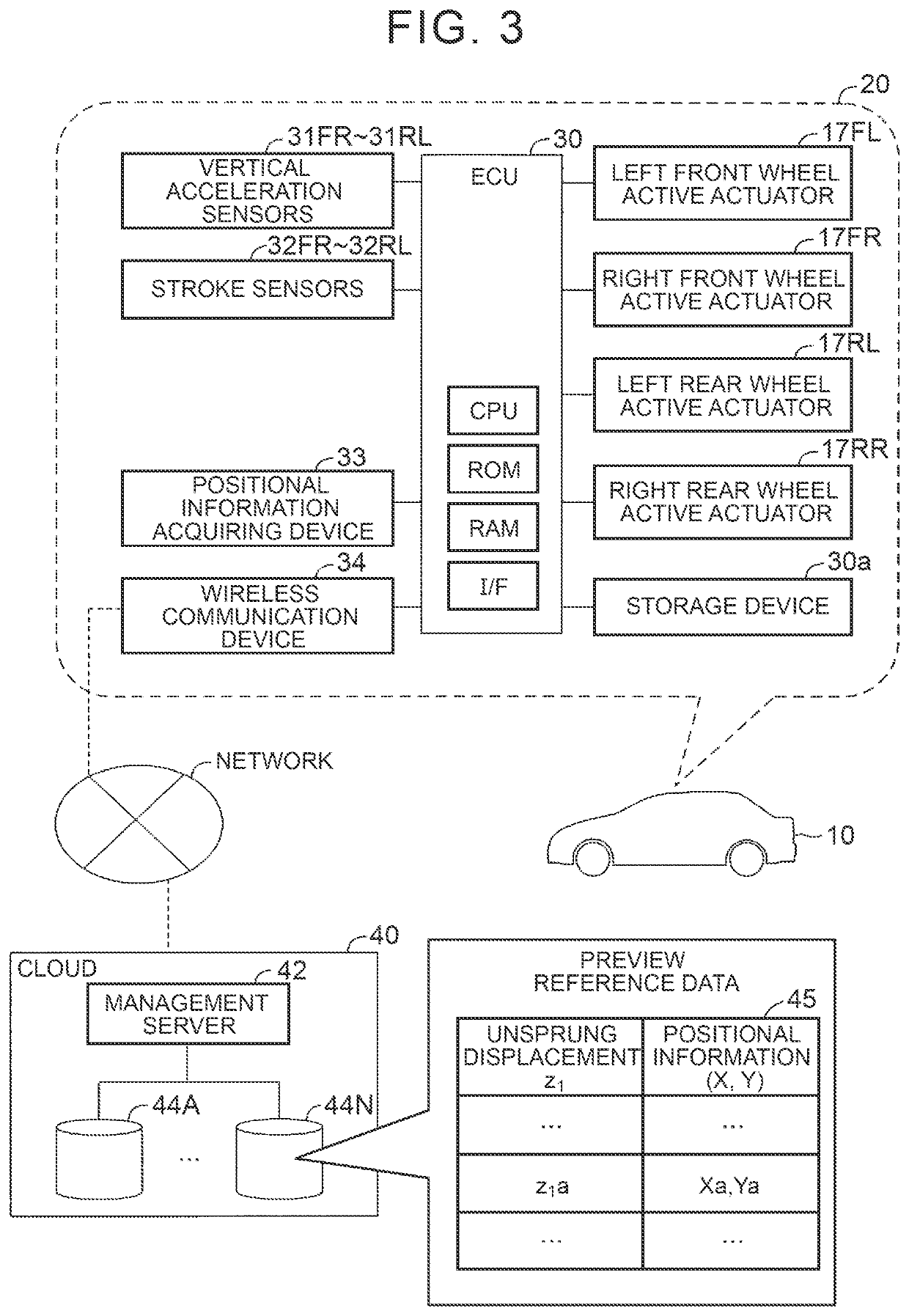
[0145]A first modified example differs from the first device only in that the unsprung displacement z1 that may include a deviation as described below is determined to reduce the deviation, and is saved as the preview reference data 45. The deviation contained in the unsprung displacement z1 is described below.

[0146]When “actual road surface displacement z0 when vehicle 10 travels at given vehicle speed V1a” is an input and “unsprung displacement z1 acquired when vehicle 10 travels on road surface in predetermined zone” is an output, a transfer function between the input and the output is defined as a transfer function (z1 / z0). A graph of FIG. 10 shows a frequency characteristic of the transfer function. That is, FIG. 10 illustrates the magnitude (gain) of the transfer function (z1 / z0) relative to a frequency f (Hz) of vibration that occurs in the unsprung portion 50 due to the road surface displacement z0.

[0147]The graph illustrated in FIG. 10 shows that the magnitude of the t...

second modified example

[0168

[0169]In a second modified example, unfiltered unsprung displacements z1 are stored as the preview reference data 45. In the preview reference data 45 of the second modified example, positional information, an unsprung displacement z1 at a position indicated by the positional information, and a vehicle speed V1 during traveling at the position are linked to each other. In the second modified example, the ECU 30 acquires, from the cloud 40, a plurality of “unsprung displacements z1, vehicle speeds V1, and pieces of positional information” in a sampling zone including a predicted passing position.

[0170]The ECU 30 calculates an average vehicle speed V1ave of the vehicle 10 when the vehicle 10 travels in the sampling zone based on the acquired vehicle speeds V1 in the sampling zone. The ECU 30 calculates time series variations of unsprung displacements z1 in the sampling zone (hereinafter referred to as “sampled displacements z1”) when the vehicle 10 travels in the sampling zone at...


PUM


Abstract

A damping control device is configured to acquire, as a preview condition amount, an unsprung condition amount at a predicted passing position where a wheel of a vehicle is predicted to pass, based on preview reference data being sets of data in which unsprung condition amounts and pieces of positional information of the wheel are linked to each other. The unsprung condition amounts indicate a displacement condition of an unsprung portion displaced in a vertical direction due to a displacement of a road surface acquired when the vehicle has traveled on the road surface. The damping control device is configured to execute, at a timing when the wheel passes through the predicted passing position, preview damping control to cause control force to agree with a target control force.

Description

CROSS-REFERENCE TO RELATED APPLICATION[0001]This application claims priority to Japanese Patent Application No. 2020-079732 filed on Apr. 28, 2020, incorporated herein by reference in its entirety.BACKGROUND1. Technical Field[0002]The present disclosure relates to a damping control device for a vehicle, a damping control system, a damping control method, and a data providing device. The damping control device for the vehicle, the damping control system, the damping control method, and the data providing device are used to, for example, acquire an unsprung condition amount at a predicted passing position where a wheel is predicted to pass, and control a control force for damping a sprung portion based on the acquired unsprung condition amount.2. Description of Related Art[0003]There is known a damping control device for a vehicle, which is configured to calculate a target control force for damping a sprung portion based on a displacement of a road surface ahead of a current contact p...

Claims


Application Information

Patent Timeline
Patent Type & Authority Applications(United States)
IPC IPC(8): B60G17/018B60G17/0165
CPCB60G17/018B60G17/0165B60G2600/60B60G2400/91B60G2500/10B60G2400/252B60G17/0157B60G17/06B60G2202/30B60G15/00B60G2400/102B60G2400/204B60G2401/16B60G2600/11B60G2401/142B60G2202/12B60G2600/02B60G17/015
Inventor FURUTA, HIROKI
Owner TOYOTA JIDOSHA KK
Why Eureka
Try Eureka