Smoke removal device

a technology of smoke removal device and smoke removal, which is applied in the direction of combustion type, stove or range, domestic heating type, etc., can solve the problems of burning off smoke, etc., and achieve the effect of effectively removing smok

Active Publication Date: 2021-10-28
GRAND MATE
View PDF0 Cites 2 Cited by
  • Summary
  • Abstract
  • Description
  • Claims
  • Application Information

AI Technical Summary

Benefits of technology

[0006]In view of the above, the primary objective of the present invention is to provide a smoke removal device which is able to effectively remove smoke.
[0008]With the smoke removal device, the smoke could be burned off when the smoke touches the flame. The first heat storage mesh and the second heat storage mesh could slow down the flow rate of the flame and increase the temperature of the heat storage meshes, so that the smoke could be burned off by touching the heat storage meshes, thereby to achieve a good smoke removal effect. Additionally, the odor of the smoke could be eliminated by burning as well.

Problems solved by technology

With the smoke removal device, the smoke could be burned off when the smoke touches the flame.

Method used


Image

  • Smoke removal device
  • Smoke removal device
  • Smoke removal device

Examples


Embodiment Construction

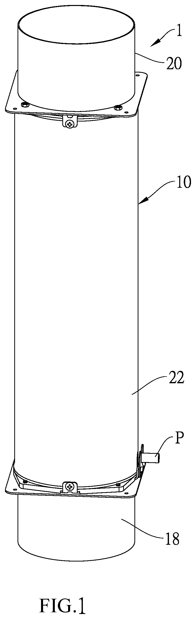
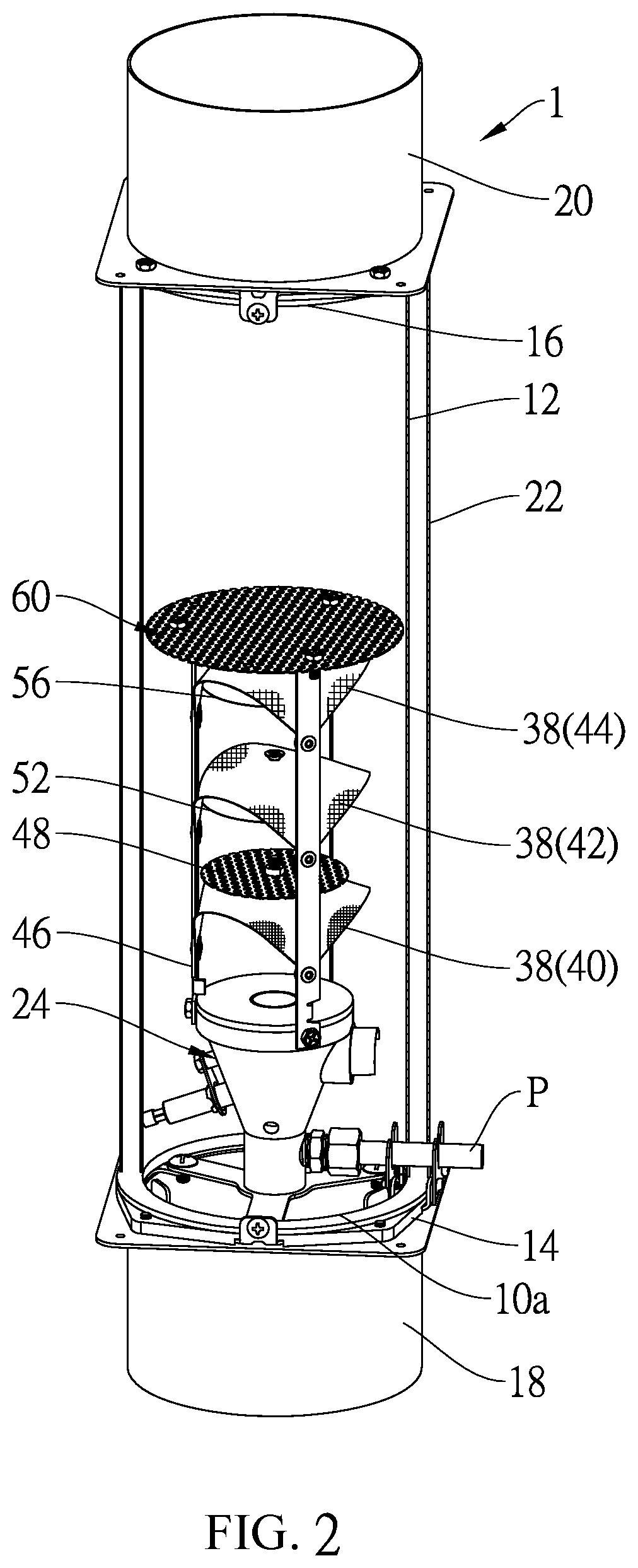
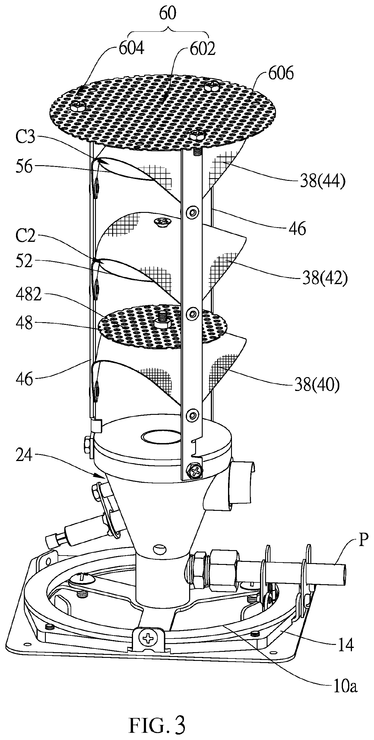
[0022]As illustrated in FIG. 1 to FIG. 9, a smoke removal device 1 of a first embodiment according to the present invention is disposed on a smoke-exhausting path and includes a connecting tube 10, a burner 24, and a plurality of heat storage meshes 38. The smoke-exhausting path could be a smoke-exhausting duct of a combustion appliance or an exhaust hood.

[0023]The connecting tube 10 has an inlet end 10a and an outlet end 10b. More specifically, the connecting tube 10 includes a tube body 12, a first connecting seat 14, and a second connecting seat 16. The first connecting seat 14 has the inlet end 10a and is connected to an inlet tube 18. The second connecting seat 16 has the outlet end 10b and is connected to an outlet tube 20. An outer surface of the tube body 12 is fitted around by an outer tube 22, wherein a gap is formed between the external tube 22 and the tube body 12.

[0024]The burner 24 is disposed in the connecting tube 10, wherein the burner 24 has a flame outlet 24a whic...


PUM


Abstract

A smoke removal device includes a connecting tube, a burner, and a plurality of heat storage meshes. The connecting tube has an inlet end and an outlet end. The burner is disposed in the connecting tube and has a flame outlet. The heat storage meshes are sequentially disposed between the flame outlet and the outlet end. The heat storage meshes includes a first heat storage mesh and a second heat storage mesh. The first heat storage mesh is located between the second heat storage mesh and the flame outlet. A mesh-number of per unit area of the first heat storage mesh is larger than that of the second heat storage mesh. The first heat storage mesh and the second heat storage mesh could slow down a flow rate of flame to increase temperatures of the heat storage meshes. The smoke is burned off once touching the heat storage meshes.

Description

BACKGROUND OF THE INVENTIONTechnical Field[0001]The present invention relates generally to a smoke removal device for an air-exhausting passage, and more particularly to a smoke removal device which removes the smoke by flame.Description of Related Art[0002]During a process of burning substances of a conventional combustion appliance (e.g. a furnace, a burner, or a coffee bean roaster), microparticles are generated. At the same time, the heat energy supplied by the combustion appliance changes a density of air, thereby to generate an air flow and form a smoke. The microparticles are distributed in the smoke and are discharged from the combustion appliance with the smoke and spreads in an environment. Besides, except the combustion appliance, oil fumes generated during cooking will spread in the environment as well.[0003]The smoke drifting in the environment causes pollution. The microparticles are quite small and light, so that the microparticles are easily spread along with the air...

Claims


Application Information

Patent Timeline
Patent Type & Authority Applications(United States)
IPC IPC(8): F23J11/02F24C15/20F23G7/06
CPCF23J11/02F24C15/2042F23G7/063F23G2209/14F23G7/065F23J13/00F23J2219/20F23J2900/15004F23J15/022F24C15/2035
Inventor HUANG, CHUNG-CHINHUANG, CHIN-YINGHUANG, HSIN-MINGHUANG, HSING-HSIUNGYEH, YEN-JENLIN, KUAN-CHOU
Owner GRAND MATE
Why Eureka
Try Eureka