Common-path cube corner interferometer and interference technique

a common-path cube and interferometer technology, applied in the field of cube corner interferometers, can solve the problems of large instrument errors, change of optical path difference, obvious jitter of interference fringes of interferometers, etc., and achieve the effects of reducing the influence of environmental interference, low beam energy utilization, and easy interference by external environments

Active Publication Date: 2021-10-28
XI'AN INST OF OPTICS & FINE MECHANICS - CHINESE ACAD OF SCI
View PDF0 Cites 0 Cited by
  • Summary
  • Abstract
  • Description
  • Claims
  • Application Information

AI Technical Summary

Benefits of technology

[0005]The present disclosure aims at providing a common-path cube corner interferometer which overcomes defects that traditional Sagnac interferometers are easily interfered by external environments and have low utilization of beam energy. According to the present disclosure, a right-angled cube-corner retroreflector (also called a cube-corner prism) is used to repl...

Problems solved by technology

Being an extremely sensitive component, even in almost vibration-free environments, an interferometer may have obvious jitters in interference fringes due to slight air disturbance or stress changes.
The non-common-path interferometer, such as the Michelson interferometer and the M-Z interferometer, is susceptible to disturbance from external thermodynamic deformation, resulting in the change of optical...

Method used


Image

  • Common-path cube corner interferometer and interference technique
  • Common-path cube corner interferometer and interference technique

Examples


embodiment 1

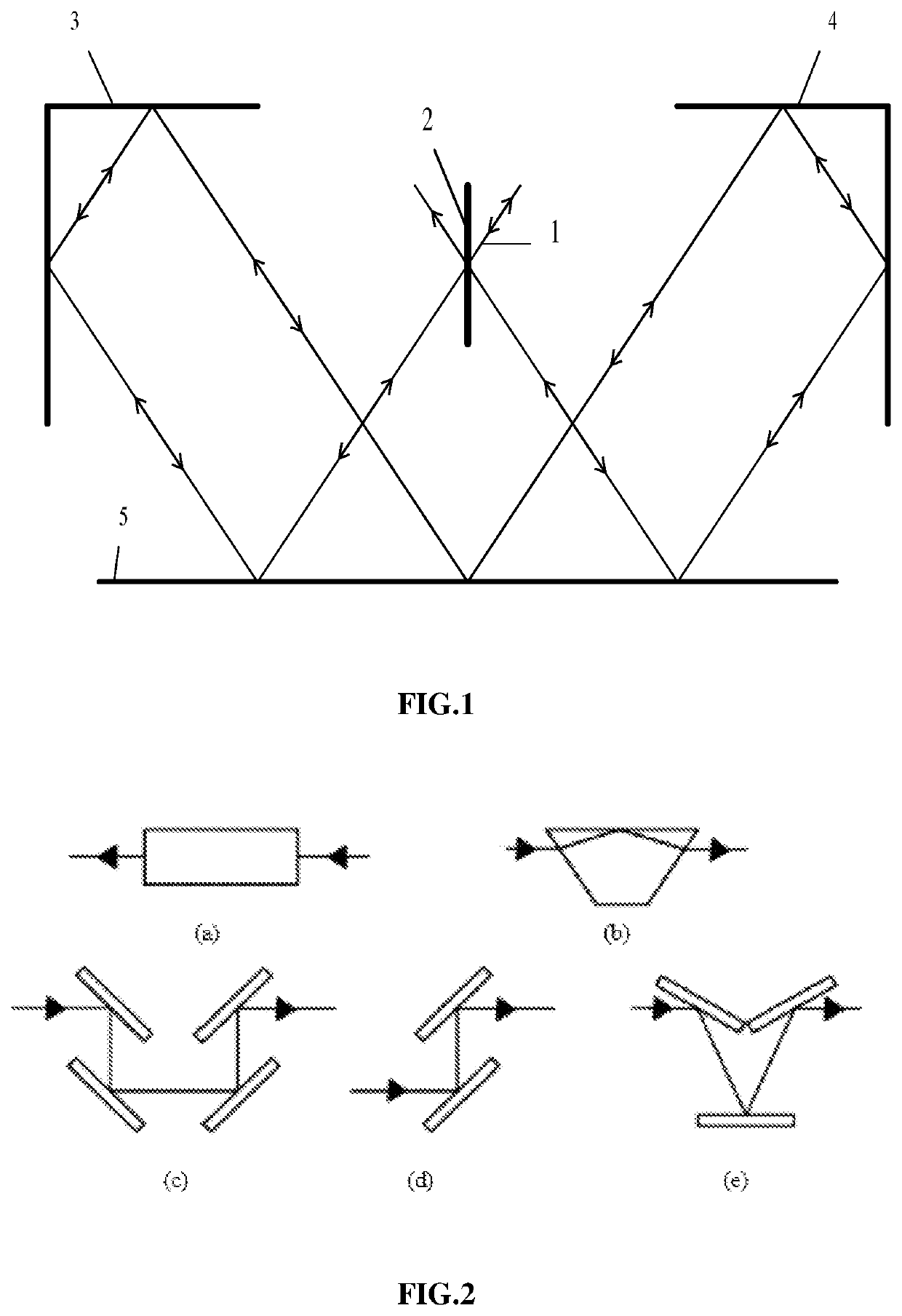
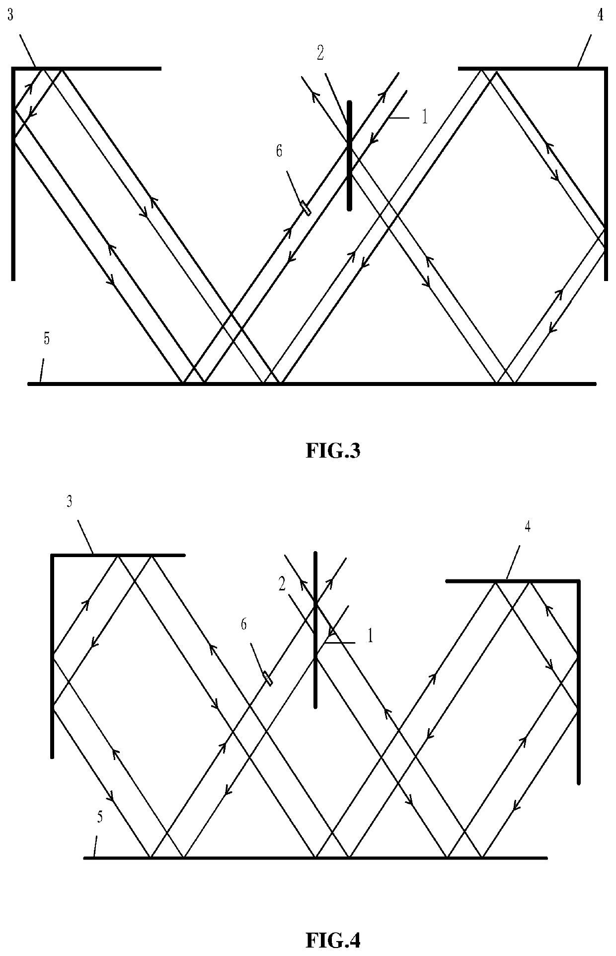
[0039]In this embodiment, the common-path cube-corner interferometer as shown in FIG. 3 adopts an asymmetric common-path beam splitting structure having right-angled cube-corner retroreflectors with a large optical path difference, including a semi-transmissive and semi-reflective beam splitter 2, a first right-angled cube-corner retroreflector 3, a second right-angled cube-corner retroreflector 4, a plane mirror 5, an optical path difference element 6. In this embodiment, a prism is selected as the optical path difference element 6, and the right-angled cube-corner retroreflectors are all two-sided ones.

[0040]The asymmetric structure of the common-path cube-corner interferometer in this embodiment is embodied in that the first right-angled cube-corner retroreflector 3 and the second right-angled cube-corner retroreflector 4 are at different distances from the semi-transmissive and semi-reflective beam splitter 2.

[0041]Incident light 1 enters the common-path cube-corner interferomet...

embodiment 2

[0049]As shown in FIG. 4, a difference between this Embodiment 2 and the above-mentioned Embodiment 1 is that: the asymmetric structure of the common-path cube-corner interferometer is embodied in that the first right-angled cube-corner retroreflector 3 and the second right-angled cube-corner retroreflector 4 are at different distances from the plane mirror 2.


PUM


Abstract

The present disclosure relates to a common-path cube-corner retroreflector interferometer with a large optical path difference and high stability, and an interference technique thereof. The interferometer adopts an asymmetric common-path beam splitting structure using right-angled cube-corner retroreflectors, comprising a semi-transmissive and semi-reflective beam splitter, a plane mirror, a first right-angled cube-corner retroreflector, a second right-angled cube-corner retroreflector and an optical path difference element. The incident light is divided into a first transmitted beam and a second reflected beam, which are respectively reflected by the plane mirror and the right-angled cube-corner retroreflectors several times and then split again, two beams of which become interference outputs along directions perpendicular to an incident direction of the incident light, and the other two beams become interference outputs along directions parallel to the incident light. The present disclosure also provides an interference technique based on the interferometer described above.

Description

CROSS REFERENCE TO RELATED APPLICATION(S)[0001]This patent application claims the benefit and priority of Chinese Patent Application No. 202010344002.8, filed on Apr. 27, 2020, the disclosure of which is incorporated by reference herein in its entirety as part of the present application.TECHNICAL FIELD[0002]The present disclosure relates to a cube corner interferometer used in the spectrum measurement technology, and in particular to a common-path cube-corner retroreflector interferometer with a large optical path difference and high stability, and an interference technique thereof.BACKGROUND ART[0003]Interferometers utilize the superposition of waves to obtain phase information of waves, so as to obtain physical quantities of concern for experiments. Interferometers are widely used in precision measurement fields such as astronomy, optics, engineering surveying, oceanography, spectrum analysis, remote sensing, and radars.[0004]Being an extremely sensitive component, even in almost ...

Claims


Application Information

Patent Timeline
IPC IPC(8): G01J3/02G01J3/45
CPCG01J3/0208G01J3/45G01J3/0243G01J3/4532G01J3/4535
Inventor WEI, RUYIDI, LAMEI
Owner XI'AN INST OF OPTICS & FINE MECHANICS - CHINESE ACAD OF SCI
Why Eureka
Try Eureka