Method of designing, configuring and accessing a modular self-storage facility

a self-storage facility and modular technology, applied in the field of storage, can solve the problems of large, multi-story buildings that are not easily re-purposed by a future user, and achieve the effects of efficient design and use, high demand, and easy scaling up of storage facilities

Inactive Publication Date: 2021-10-28
SNL FUND LLC
View PDF18 Cites 2 Cited by
  • Summary
  • Abstract
  • Description
  • Claims
  • Application Information

AI Technical Summary

Benefits of technology

[0007]The present invention is generally directed to a method of designing, configuring and accessing a self-storage facility that utilizes shipping containers and / or other pre-fabricated portable storage containers that can be arranged next to each other and stacked on top of each other (e.g., from largest to smallest) in a way that provides an efficient design and use along with easy access to the facility and units and the ability for consumers to utilize what are in-effect, internal corridors.
[0008]The present invention is scalable and as such adaptable depending on consumer demand. If the demand is high, the storage facility can be scaled up. If the demand is low, the storage facility can be scaled down by relocating the shipping containers to another facility or selling them back into the market. This may alleviate a concern of a municipality who has approval jurisdiction over such facilities. That is, if a facility operator determines to close a facility as a result of lower demand than forecast, a large, multi-story building will be left behind that is not easily re-purposed by a future user. The modularity and scalability of the present invention eliminates that potential concern.
[0009]Customers want the well-lit, secure storage that a modern storage facility building offers as well as the ability to drive their vehicle to their storage unit that is offered by drive-up storage facilities. In an embodiment, the present invention allows customers to drive their vehicle to a lift and drop off their items without physically having to carry the items up a flight or flights of stairs and utilize stairs to access the upper floors. The stairs and lift can be interior facing for the upper levels. By turning the second level doors to the interior, contrary to the first level, a secure access hallway on the upper level can be created by utilizing the exterior roof of the lower unit as the floor. This also eliminates the need to build an exterior walkway with a safety railing. In an embodiment, the lift can be operated by an employee of the facility who can assist with loading of storage items and will operate the lift. Alternatively, the lift can be unmanned that is accessed without employee assistance. The upper floors can have carts / dollies which the customers then may use to transport their items to their unit. Alternatively, if a car or truck lift is used, the user may back the car on to the lift and then unload the materials directly on to the upper floor. The storage facility can further include a roof arranged above the uppermost level to protect customers / storage unit owners from the environments (e.g., sun, rain, snow, etc.).
[0010]The storage facility can further include an office that is a modular prefabricated custom space that can be made out of a shipping container. It can be designed off site and delivered nearly completed, ready to be installed. Modern automation systems for self-storage operations can be implemented, including online / app-based unit rentals, kiosks which distribute locks and state of the art security, actively monitored by closed-caption television (CCTV). The facilities can also be designed to be eco-friendly, low-energy consuming, utilizing solar power, where possible, and eco-friendly lighting. The roof for each stack is designed for solar as well.
[0011]The overall system creates a self-storage product that commoditizes much of the development and construction process. It allows for the engineering, design and the majority of construction to take place offsite, significantly reducing the time it takes to render a facility operational. It creates the ability to have a modular storage facility, rapidly moving from acquisition to operation to meet current demand.

Problems solved by technology

That is, if a facility operator determines to close a facility as a result of lower demand than forecast, a large, multi-story building will be left behind that is not easily re-purposed by a future user.

Method used


Image

  • Method of designing, configuring and accessing a modular self-storage facility
  • Method of designing, configuring and accessing a modular self-storage facility
  • Method of designing, configuring and accessing a modular self-storage facility

Examples


Embodiment Construction

[0021]With reference now to the drawings, and in particular FIGS. 1-49, embodiments of the self-storage facilities of the present disclosure will be described.

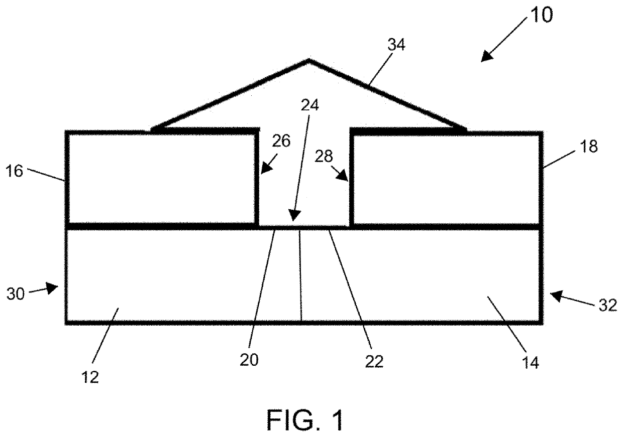
[0022]FIG. 1 illustrates a storage facility 10 that includes a plurality of units 12, 14, 16, 18 that are arranged adjacent to each other, stacked on top of each other and / or abut each other. It is noted that for simplicity FIG. 1 is a side view of the storage facility 10 that depicts four units 12, 14, 16, 18. However, the number of units that are part of the storage facility 10 and the configuration of said units should not be limited to the number and / or configuration depicted in FIG. 1. Any number and any configuration of units can be utilized. That said, regardless of the number of units and size of units, as depicted in FIG. 1, the largest units (here units 12, 14) will be arranged at the base of the storage facility 10 on the ground level. The next largest units (here 16, 18) will be arranged on top of (stacked on) the ...


PUM


Abstract

A storage facility and a method of designing, configuring, reconfiguring and accessing a modular self-storage facility that utilizes shipping containers and/or other pre-fabricated portable storage containers that can be arranged next to each other and stacked on top of each other in a way that provides an efficient design and use along with easy access to the facility and units and the ability for consumers to utilize what are in-effect, internal corridors.

Description

CROSS-REFERENCE TO RELATED APPLICATIONS[0001]This application claims priority to U.S. Provisional Patent Application No. 63 / 013,771, filed on Apr. 22, 2020, and U.S. Provisional Patent Application No. 63 / 073,577, filed on Sep. 2, 2020, the contents of each are incorporated herein by reference in their entirety.FIELD OF THE INVENTION[0002]The present disclosure is directed generally to storage and more particularly to a method of designing, configuring, reconfiguring and accessing a modular self-storage facility.BACKGROUND OF THE INVENTION[0003]First generation self-storage facilities were designed as single-story, row-style, slab-on-grade buildings with unit access doors in front of the unit. Unit renters were able (and for those that still use these storage facilities are able) to drive up to the door of their assigned unit and load and unload desired items into and out of their unit. Unit renters benefited from the ability to unload items from their vehicle in close proximity to t...

Claims


Application Information

Patent Timeline
Patent Type & Authority Applications(United States)
IPC IPC(8): G06F30/13G06F30/17
CPCG06F30/13G06F30/17G06F2111/20E04H1/005E04H2001/1283
Inventor SHARINN, MARC
Owner SNL FUND LLC
Why Eureka
Try Eureka