Shearable Sleeve

a sleeve and strap technology, applied in the direction of sealing/packing, well equipment, construction, etc., can solve the problems of slipping into the well, no radial support of the tab, and damage to the pump or other components used in the well, so as to simplify the construction and ensure the reliability of us

Active Publication Date: 2021-11-04
NINE DOWNHOLE TECHNOLOLGIES LLC
View PDF0 Cites 2 Cited by
  • Summary
  • Abstract
  • Description
  • Claims
  • Application Information

AI Technical Summary

Benefits of technology

[0013]In any of the disclosed embodiments of the shearable sleeve, the shearable sleeve may be provided and used as a unitary part, such as a pre-assembled assembly of parts, which may significantly simplify construction and reliability of use. The shearable sleeve may be made from a metal alloy such as aluminium bronze, nickel bronze or nickel aluminium bronze.

Problems solved by technology

A disadvantage of several of the known disintegrable plugs is that residues from the plug element itself or from plugs seats, shearing devices, loading devices and or other parts of activation mechanisms may become loose and may enter the well stream, potentially damaging well equipment such as pumps or other components used in the circulation of well fluids after opening of the plug.
When the plug element disintegrates, the tabs may have no radial support and may fall into the well.

Method used


Image

  • Shearable Sleeve
  • Shearable Sleeve
  • Shearable Sleeve

Examples


first embodiment

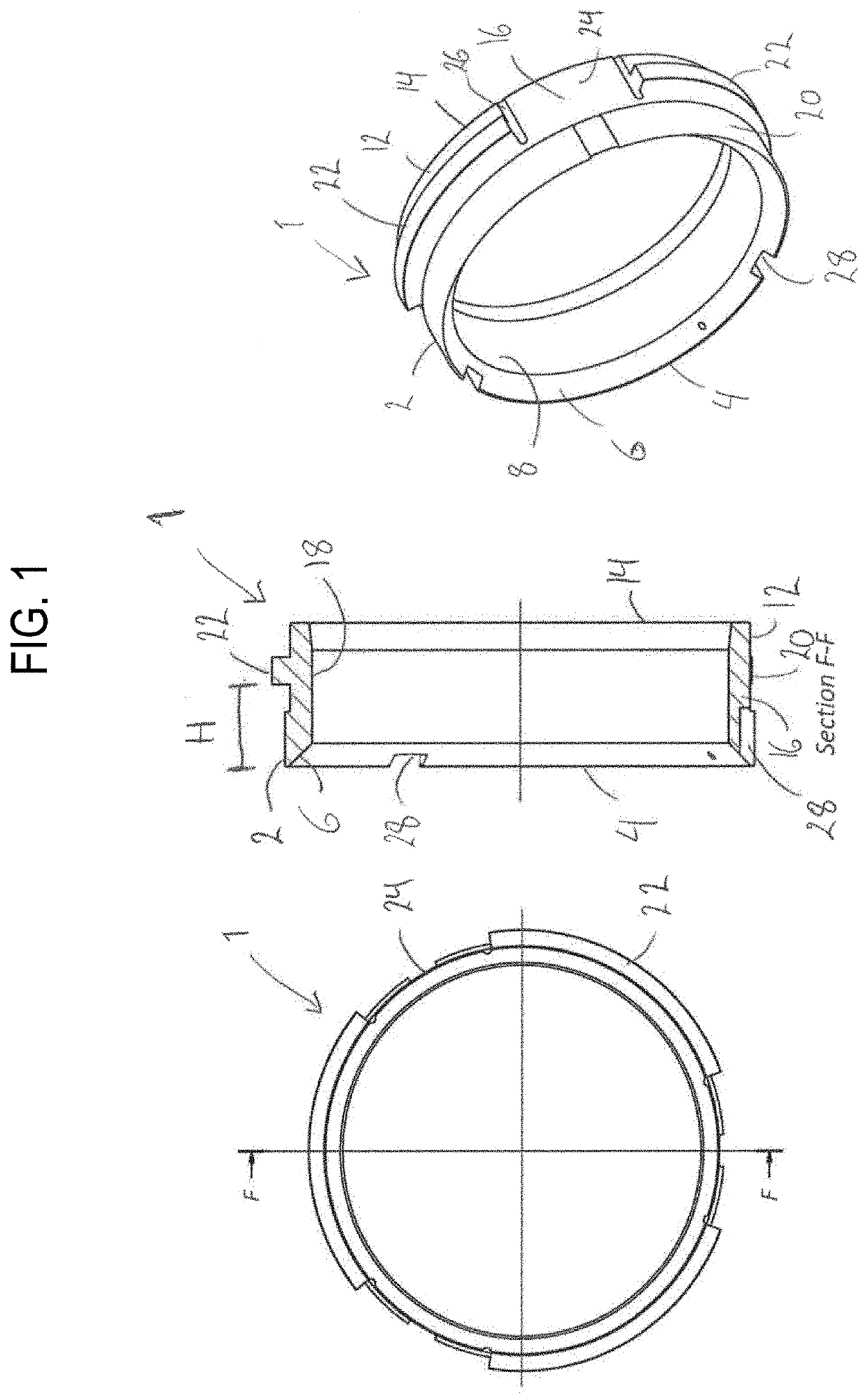
[0038]In FIG. 1 a shearable sleeve 1 is shown in a top view to the left, in a cross-sectional axial view in the middle, and in a perspective view to the right. The shearable sleeve 1, which is formed substantially cylindrically, has a first portion 2, including a first circumferential end surface 4. The first portion 2 includes a seat 6 adapted to support a disintegrable plug element 8 (as shown in FIGS. 2-4) in use. Opposite the first portion 2, the shearable sleeve 1 is provided with a second portion 12 including a second circumferential end surface 14. Between the first circumferential end surface 4 and the second circumferential end surface 14, a substantially cylinder-shaped surface 16 is shown extending.

[0039]In use of embodiment shown in FIG. 1, the first portion 2 may define an upper portion of the shearable sleeve 1, while the second portion 12 may define a lower portion. The cylinder surface 16 may have a substantially smooth inner portion 18. From an outer portion 20 of t...

second embodiment

[0056]FIG. 6 shows a shearable sleeve 1. A top view is shown to the left, a cross-sectional axial view F-F in the middle and a perspective view to the right. The shearable sleeve 1 of FIG. 6 has a slightly different geometric configuration than the shearable sleeve 1 of FIG. 1, though the functionality is similar. As shown in FIG. 6, each of the radial protrusions 22 may cover only about 45° of the circumference of the outer portion 20 of the surface 16, while the gap 24 between each protrusion may covers about 90°.

[0057]The shearable sleeve 1 shown in FIG. 6 may be particularly adapted to withstand pressures up to 5,000 psi of pressure before activation and shearing, while the shearable sleeve 1 of FIG. 1 may be particularly adapted to withstand 10,000 psi of pressure, as mentioned above. The radial protrusions 22 may be provided substantially half-way between the first circumferential end surface 4 and the second circumferential end surface 14, and may be slightly closer to the up...


PUM


Abstract

A shearable sleeve supports a disintegrable plug element in a pipe string, and may include a first portion including a first circumferential end surface, a seat for supporting the disintegrable plug element, a second portion including a second circumferential end surface, and a surface extending axially between the first and second circumferential end surfaces and formed with one or more radial protrusions adapted to shear off from the rest of the sleeve when being exposed to a predefined axial force, and one or more recesses for receiving one or more loading devices for initiating disintegration of the disintegrable plug element upon contact with the plug, wherein one or more radial protrusions is/are axially offset relative to the first circumferential end surface. A plug device, as well as a plug assembly in a pipe string, may include the shearable sleeve.

Description

CROSS REFERENCE TO RELATED APPLICATIONS[0001]The application claims benefit of priority from Norweigian Patent Application No. 20200520, filed May 4, 2020, titled SHEARABLE SLEEVE, which is incorporated herein by reference in its entirety for all purposes.BACKGROUNDField of the Disclosure[0002]The present disclosure relates to a shearable sleeve. More specifically the disclosure relates to a shearable sleeve for supporting a disintegrable plug element in a pipe string. The disclosure also relates to a plug device, as well as a plug assembly in a pipe string, including such a shearable sleeve.Description of the Related Art[0003]Disintegrable plugs, such as glass plugs and ceramic plugs, are known from the prior art. Disintegrable plugs are also known where disintegration of the plug element may be initiated by means of hydraulic pressure controlled from topside, which reduces the need for interventions runs into the well. A disadvantage of several of the known disintegrable plugs is ...

Claims


Application Information

Patent Timeline
Patent Type & Authority Applications(United States)
IPC IPC(8): E21B33/12E21B33/128
CPCE21B33/1208E21B33/128E21B34/063E21B33/12E21B2200/05
Inventor BRANDSDAL, VIGGO
Owner NINE DOWNHOLE TECHNOLOLGIES LLC
Why Eureka
Try Eureka