
Seal ring structure

Active Publication Date: 2021-11-11
UNITED MICROELECTRONICS CORP
View PDF3 Cites 0 Cited by
  • Summary
  • Abstract
  • Description
  • Claims
  • Application Information

AI Technical Summary

Benefits of technology

The invention includes a structure that prevents moisture from entering the circuit elements, using a fence-shaped seal structure between the inner and outer seal rings. This structure is designed to not completely contact the rings, allowing for a small gap and minimal impact on signal transmission. The seal ring at the corner is designed as a bevel edge, providing additional protection for the central circuit element. Essentially, this invention ensures the continued performance of the circuit elements while preventing moisture damage.

Problems solved by technology

However, this structure will cause a problem in that the signal of the pad will be coupled to the sealing ring, causing signal interference.
In addition, since the RF circuit is used for signal transmission, the sealing ring will also block the signal transmission of the RF circuit.

Method used


Image

  • Seal ring structure
  • Seal ring structure
  • Seal ring structure

Examples


Embodiment Construction

[0016]To provide a better understanding of the present invention to users skilled in the technology of the present invention, preferred embodiments are detailed as follows. The preferred embodiments of the present invention are illustrated in the accompanying drawings with numbered elements to clarify the contents and the effects to be achieved.

[0017]Please note that the Figures are only for illustration and the Figures may not be to scale. The scale may be further modified according to different design considerations. When referring to the words “up” or “down” that describe the relationship between components in the text, it is well known in the art and should be clearly understood that these words refer to relative positions that can be inverted to obtain a similar structure, and these structures should therefore not be precluded from the scope of the claims in the present invention.

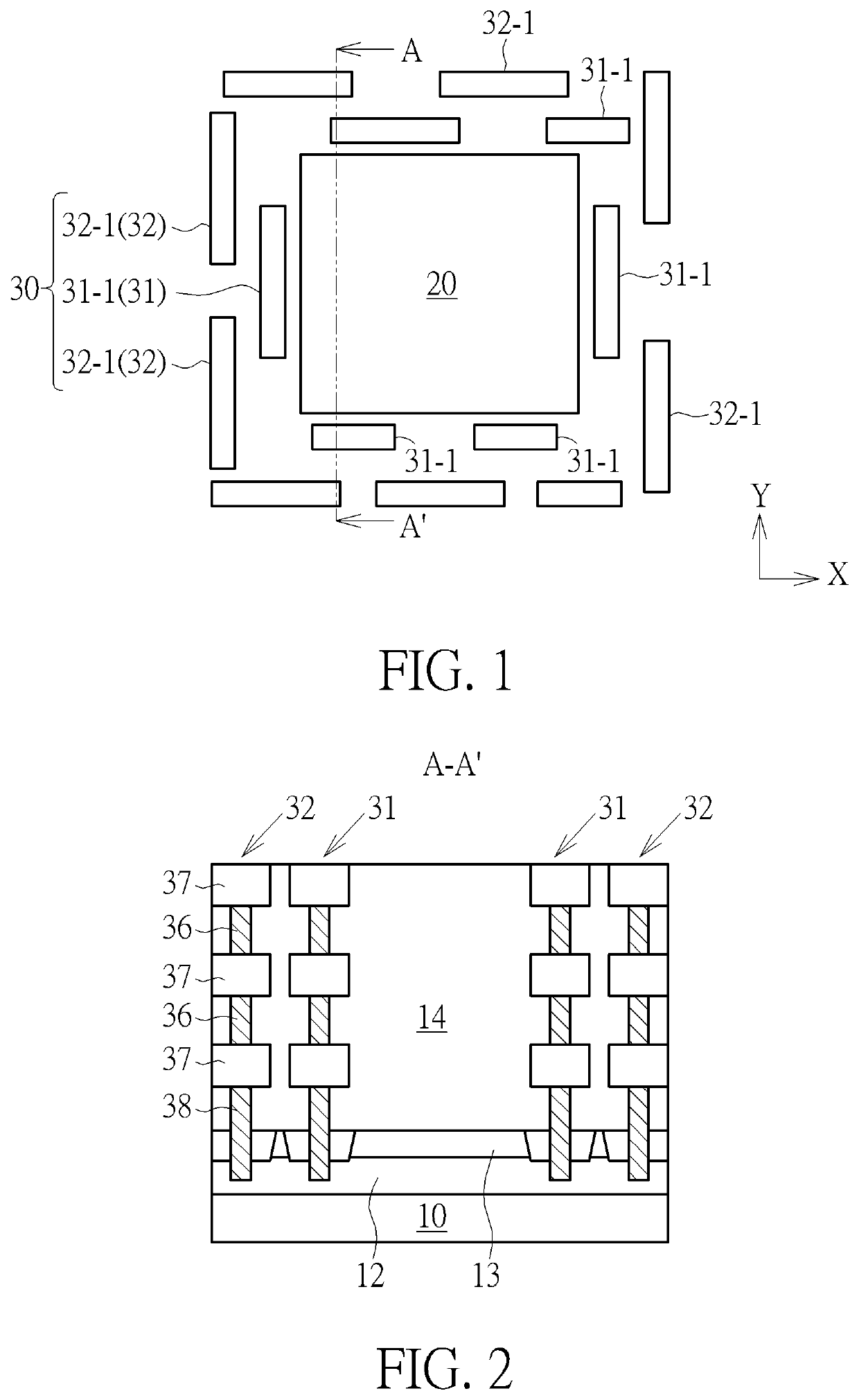
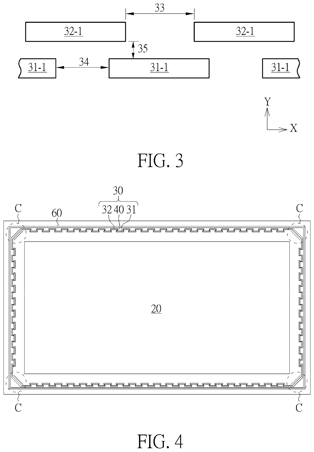
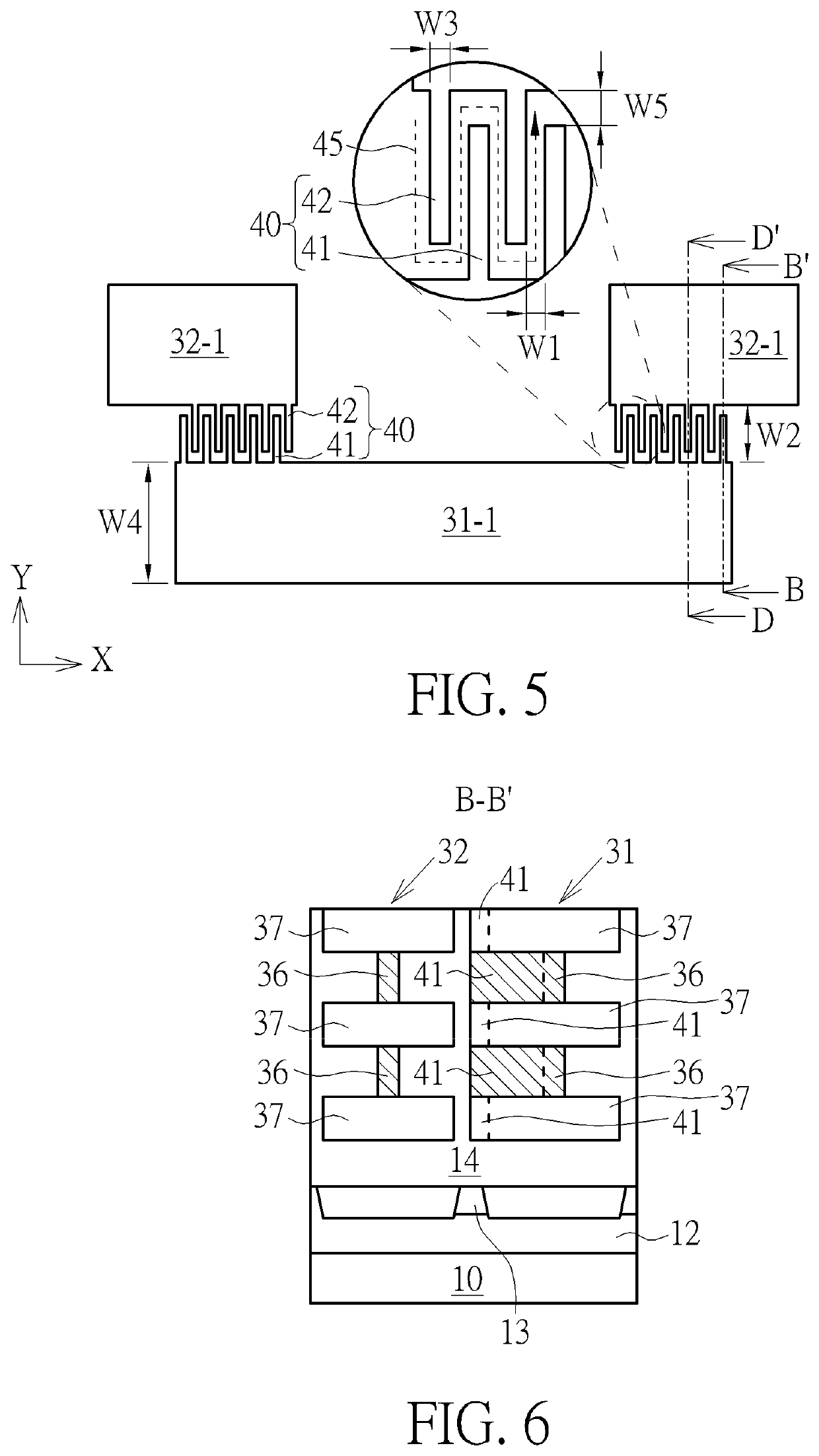
[0018]Please refer to FIGS. 1-3. FIG. 1 shows a schematic top view of a semiconductor structure acc...


PUM


Abstract

The invention provides a seal ring structure, which comprises a substrate, and a seal ring positioned on the substrate, wherein the seal ring comprises an inner seal ring comprising a plurality of inner seal units, wherein each of the inner seal units is arranged at intervals with each other, an outer seal ring comprising a plurality of outer seal units arranged at the periphery of the inner seal ring, wherein each of the outer seal units is arranged at intervals with each other, and a plurality of groups of fence-shaped seal units, wherein at least one group of fence-shaped seal units is positioned between one of the inner seal units and the other adjacent outer seal unit.

Description

BACKGROUND OF THE INVENTION1. Field of the Invention[0001]The invention relates to the field of semiconductors, in particular to a seal ring structure.2. Description of the Prior Art[0002]With the improvement of integrated circuit (IC) speed, seal ring has been integrated into equipment seal to reduce radio frequency (RF) interference and signal cross coupling. The seal ring may be grounded or connected to a grounded signal, such as a DC voltage power line, to reduce interference. In some cases, the sealing ring may be part of the seal of the device, where a conductive lid is typically connected to the sealing ring. The sealing ring may be incorporated into the IC fabrication and may include a conductive covering over the substrate.[0003]Conventional sealing rings are usually composed of one or more interconnected conductive metal layers. Seen from the top view, it is a closed shape, and the closed area of the sealing ring contains RF circuit or other pads and other components, wher...

Claims


Application Information

Patent Timeline
IPC IPC(8): F16J15/06H05K1/02H05K1/18H05K9/00
CPCF16J15/06H05K1/0243H05K2201/09009H05K9/0015H05K1/181H01L23/564H01L23/552F16J15/064H01L23/585H01L23/562
Inventor YAO, HAI BIAOXING, SULIAO, JINYUVERMA, PURAKH RAJ
Owner UNITED MICROELECTRONICS CORP
Learn More