Sheath material for battery

a battery and sheath technology, applied in the field of battery pouches, can solve the problems of increasing the internal resistance of the battery, affecting the power output characteristics, and difficult to greatly improve the power output, so as to suppress damage to the sealing portion, the effect of significantly improving the power output characteristics of the battery

Active Publication Date: 2021-11-11
LIBEST +1
View PDF0 Cites 0 Cited by
  • Summary
  • Abstract
  • Description
  • Claims
  • Application Information

AI Technical Summary

Benefits of technology

[0018]A battery pouch according to the present disclosure includes a second member layer containing an elastomer so that the second member layer can be brought into discontinuous contact with an electrode assembly. Accordingly, when an internal pressure decreases in a vacuum sealing process during assembly of a battery, an elastic and discontinuous pressure is additionally applied to the electrode assembly by the second member layer containing the elastomer. Therefore, the power output characteristics of the battery can be significantly improved. Further, a space may be formed between the second member layer containing the elastomer and the electrode assembly by discontinuous contact. Therefore, while the electrode assembly is pressed by the second member layer, it is possible to suppress damage to a sealing portion located at the edge of the battery pouch caused by a pressure applied to the sealing portion.

Problems solved by technology

In particular, the internal resistance greatly affects the power output characteristics.
In general, if materials of the two electrodes in a given battery system (lithium-ion battery, lead-acid storage battery, nickel metal hydride battery, etc.) are determined, a change in the internal resistance generated by the electrode active materials is small, and, thus, it is difficult to greatly improve the power output.
During this process, various problems of increasing the internal resistance of the battery, such as distortion of the two electrodes or formation of an empty space, occur.
However, since it requires additional components inside or outside the battery, such as a pressurizer, there is a limitation in application to an actual battery.
Currently, the most easily adoptable method for improving the power output characteristics of a currently commercial battery is to reduce the active material content and increase the carbon conductor content inside the electrodes, which entails a relative decrease in the active material content and thus causes a significant decrease in the energy density of the battery.

Method used


Image

  • Sheath material for battery
  • Sheath material for battery
  • Sheath material for battery

Examples


Embodiment Construction

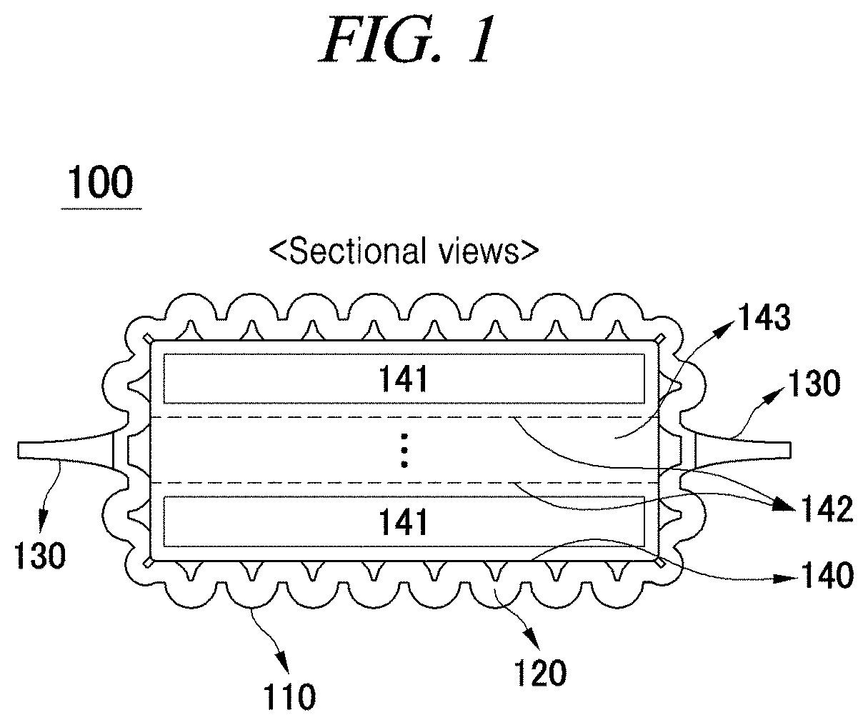
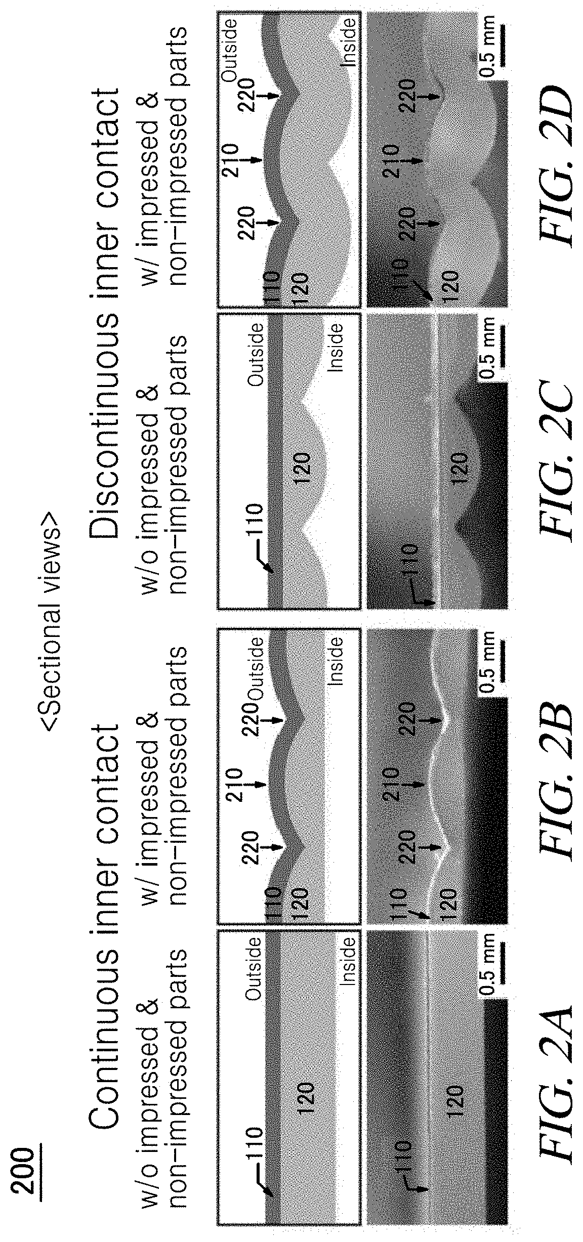
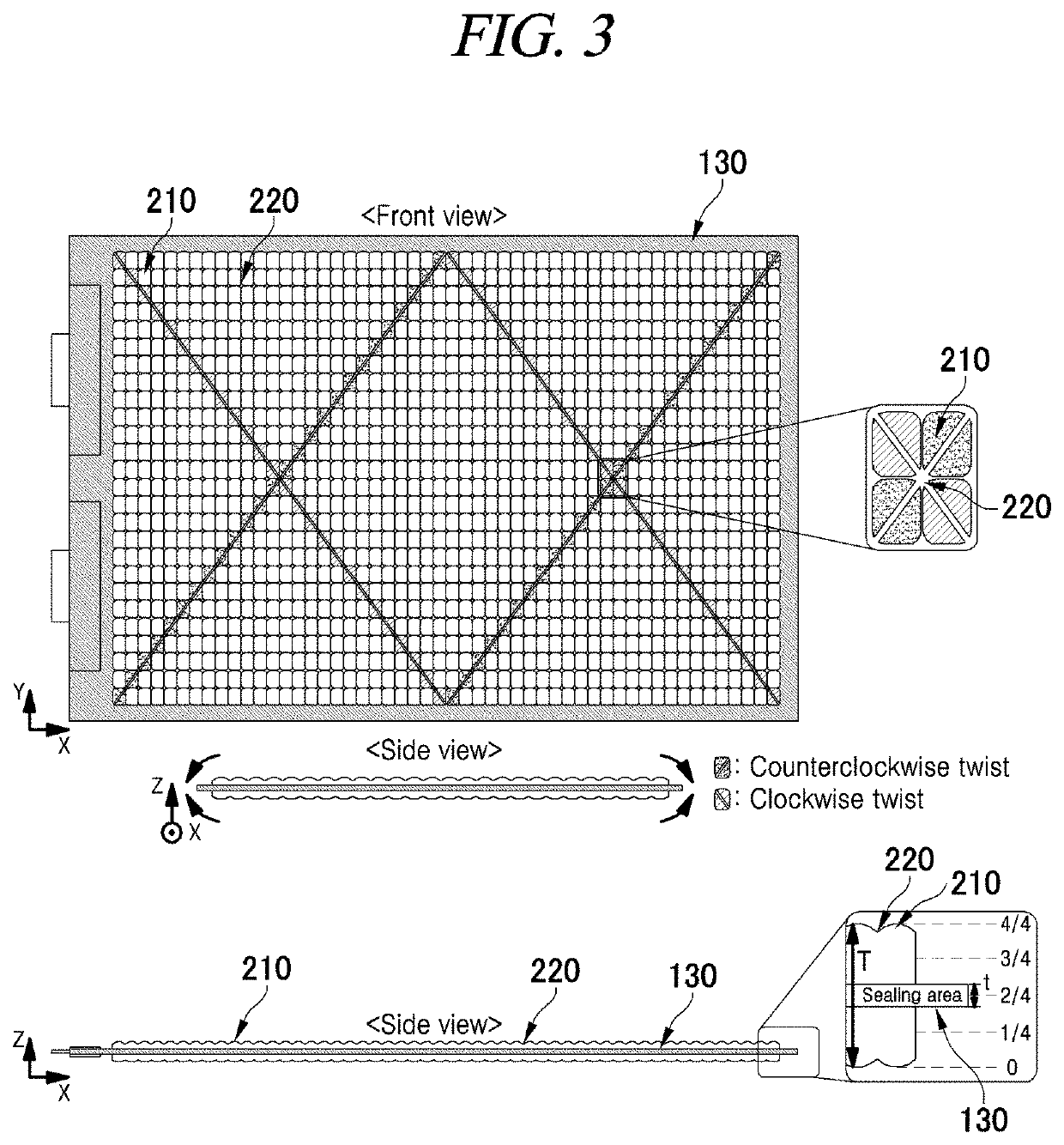
[0029]Hereinafter, the present disclosure will be described in detail.

[0030]The following exemplary embodiments are provided only for understanding of the present disclosure but not intended to limit the right scope of the present disclosure. Therefore, the equivalent inventions that perform the same functions in the same scope as the present disclosure are also included in the right scope of the present disclosure.

[0031]It is to be noted that when reference numerals refer to components of each drawing, although the same components are illustrated in different drawings, the same components are referred to by the same reference numerals as possible. Further, if it is considered that description of related known configuration or function may cloud the gist of the present disclosure, the description thereof will be omitted.

[0032]Further, in describing components of the present disclosure, terms such as first, second, A, B, (A), (B), etc. can be used. These terms are used only to differ...


PUM

PropertyMeasurementUnit
θaaaaaaaaaa
θaaaaaaaaaa
θaaaaaaaaaa

Abstract

A battery pouch that is formed to accommodate an electrode assembly, comprising: a first member layer; and a second member layer that is located between the first member layer and the electrode assembly, and contains an elastomer and protrudes toward the electrode assembly at a plurality of locations to be brought into discontinuous contact with the electrode assembly, wherein the second member layer has spaces open to the electrode assembly between the protruding portions. Accordingly, the power output characteristics of the battery can be improved and the damage to the damage to the sealing portion can be prevented.

Description

TECHNICAL FIELD[0001]The present disclosure relates to a battery pouch which accommodates an electrode assembly.BACKGROUND[0002]Various primary or secondary batteries are power supply devices configured to store chemical energy based on a redox potential difference between the negative electrode and the positive electrode, i.e., two electrodes, and convert the chemical energy into electric energy when connected to external conducting wires to enable a desired electronic device to operate. When a battery is driven to be discharged as described above, the electric energy that can be delivered at a given time corresponds to the power output, and the power output is an important index in evaluating the performance of the battery. For example, the acceleration performance of an electric vehicle is determined by the power output performance of a secondary battery installed in the electric vehicle. The power output characteristics of the battery are determined by various properties of comp...

Claims


Application Information

Patent Timeline
Patent Type & Authority Applications(United States)
IPC IPC(8): H01M50/121H01M50/105H01M10/04H01M50/10H01M50/102
CPCH01M50/121H01M10/0468H01M50/105Y02E60/10Y02P70/50H01M50/131H01M50/141H01M50/102H01M50/10
Inventor CHOI, JANG WOOKKIM, JOO SEONG
Owner LIBEST
Why Eureka
Try Eureka