Method and device for creating an environmentally sealed connection between two regions

a technology of environmental sealing and connection, which is applied in the direction of transportation and packaging, manufacturing tools, other domestic articles, etc., can solve the problems of sterile transfer of organs, uncontaminated biological tissue or samples from one containment to another, and severe risk to consumer or patient health, etc., and achieves the effect of simple operation

Pending Publication Date: 2021-11-18
LUGAIA AG
View PDF4 Cites 0 Cited by
  • Summary
  • Abstract
  • Description
  • Claims
  • Application Information

AI Technical Summary

Benefits of technology

[0016]An aim of the present invention is the generation of a joining connection between two regions which meets the desired requirements of b

Problems solved by technology

In these industries, the consequences of contaminating the enclosed volumes or regions with the external environment may result in considerable financial consequences and potentially poses a severe risk for consumer or patient health.
The same technical problem, i.e. how to safely join two regions under exclusion of the environment, pr

Method used


Image

  • Method and device for creating an environmentally sealed connection between two regions
  • Method and device for creating an environmentally sealed connection between two regions
  • Method and device for creating an environmentally sealed connection between two regions

Examples


Embodiment Construction

OF EMBODIMENTS OF THE PRESENT INVENTION

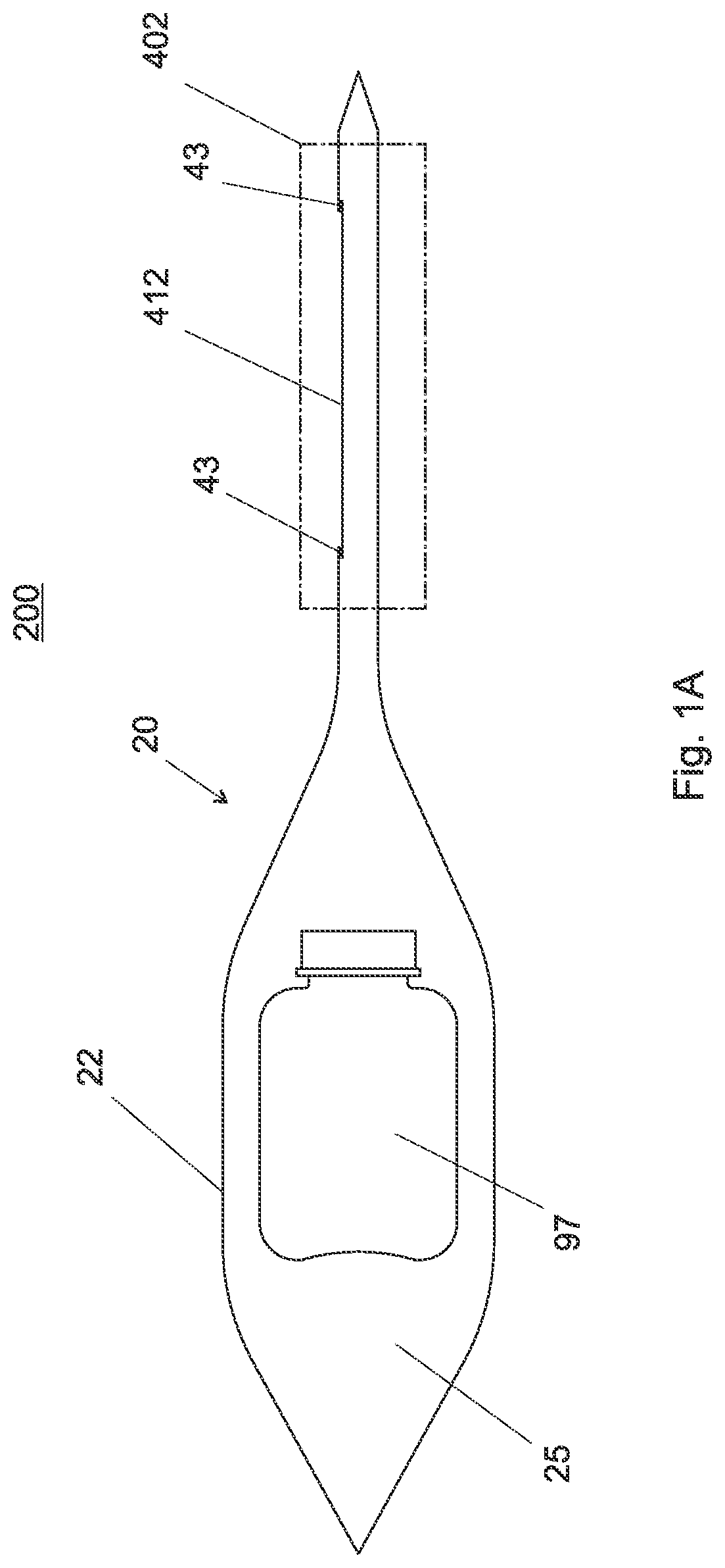
[0058]With reference to FIGS. 1A, 1B, a schematic cross section of a preferred embodiment of the at least partially flexible barriers 22, 32 confining two separate regions 25, 35 to be joined is shown. FIG. 1A exemplifies a first enclosed region 25 with a content 97, in this case a flask, for transfer. The first region 25 is confined by a sealed bag 20, which comprises a connection portion 40. The sealed bag separates the first region 25 from the external environment 200.

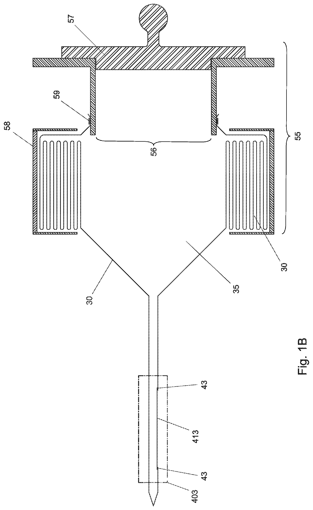
[0059]FIG. 1B shows a schematic cross section of a preferred embodiment of the at least partially flexible barrier 32 confining the second region 35. In this example, the barrier is at partially formed by an endless liner 30, which is connected to an air-lock structure 55 comprising an air lock door 57 and an air lock opening 56. The endless liner 30 is connected to the opening along a liner attachment zone 59. This attachment zone 59 constitutes a hermetic connection between l...


PUM

PropertyMeasurementUnit
Temperatureaaaaaaaaaa

Abstract

A method and device for creating an environmentally sealed connection for transfer between a first region and a second region, the first region and the second region each having an at least partially flexible barrier with connection portions, comprising the following steps: (i) superposition of said connection portions of the barriers in a sandwich arrangement, wherein each connection portion comprises a first area at least partially made of thermo-resistant material and a second area comprising a first welding band zone of a closed geometrical shape, said first and second area of each barrier being arranged to face one another, with the first areas of the two barriers forming the outside layers of the sandwich arrangement, and the second areas of the two barriers forming the inside layers of the sandwich arrangement, wherein the first areas are positioned to cover the first welding band zones of the second zones, (ii) joining the second areas by welding of the first closed welding band zones, whereby a first separation line, comprised inside and along the length of the first welding band zone, is cut as a result of the welding and whereby the barrier areas enclosed by the separation line are welded along their edges to form an insert, which becomes detached from the at least partially flexible barriers, and (iii) distancing the first areas of the super-positioned connection portions from each other, for example by pulling them apart, thereby revealing an opening confined by the welded seam connecting the second areas of the at least partially flexible barriers and joining the first region with the second region.

Description

TECHNICAL DOMAIN[0001]The present invention concerns a method and device for generating an environmentally sealed connection between two regions suited for transfer, which is not exposed to an external environment.RELATED ART[0002]Several industry sectors, such as the pharmaceutical and biotech industry, chemical industry and medical device industry, regularly face the problem of how to join a volume or region of a defined environmental condition, such as a defined contamination status, with another volume or region of the same environmental condition without exposing either of the volumes of regions to an external environment with different environmental condition. In these industries, the consequences of contaminating the enclosed volumes or regions with the external environment may result in considerable financial consequences and potentially poses a severe risk for consumer or patient health.[0003]The same technical problem, i.e. how to safely join two regions under exclusion of...

Claims


Application Information

Patent Timeline
IPC IPC(8): B23K13/02B21C37/08
CPCB23K13/025B23K2101/06B21C37/08B65B69/0008B29C65/18B29C66/43B65B55/027B29C66/71B29C66/919B29C65/38B29C66/8324B29C66/0018B29C66/849B29C66/24244B29C66/004B29C66/723B29C65/7453B29C65/7461B29K2067/003B29K2023/06B23K2103/42
Inventor SCHNYDER, VIKTOR
Owner LUGAIA AG
Why Eureka
Try Eureka