High-temperature condensation particle counter
- Summary
- Abstract
- Description
- Claims
- Application Information
AI Technical Summary
Benefits of technology
Problems solved by technology
Method used
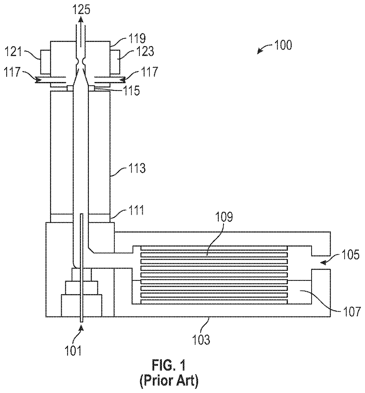
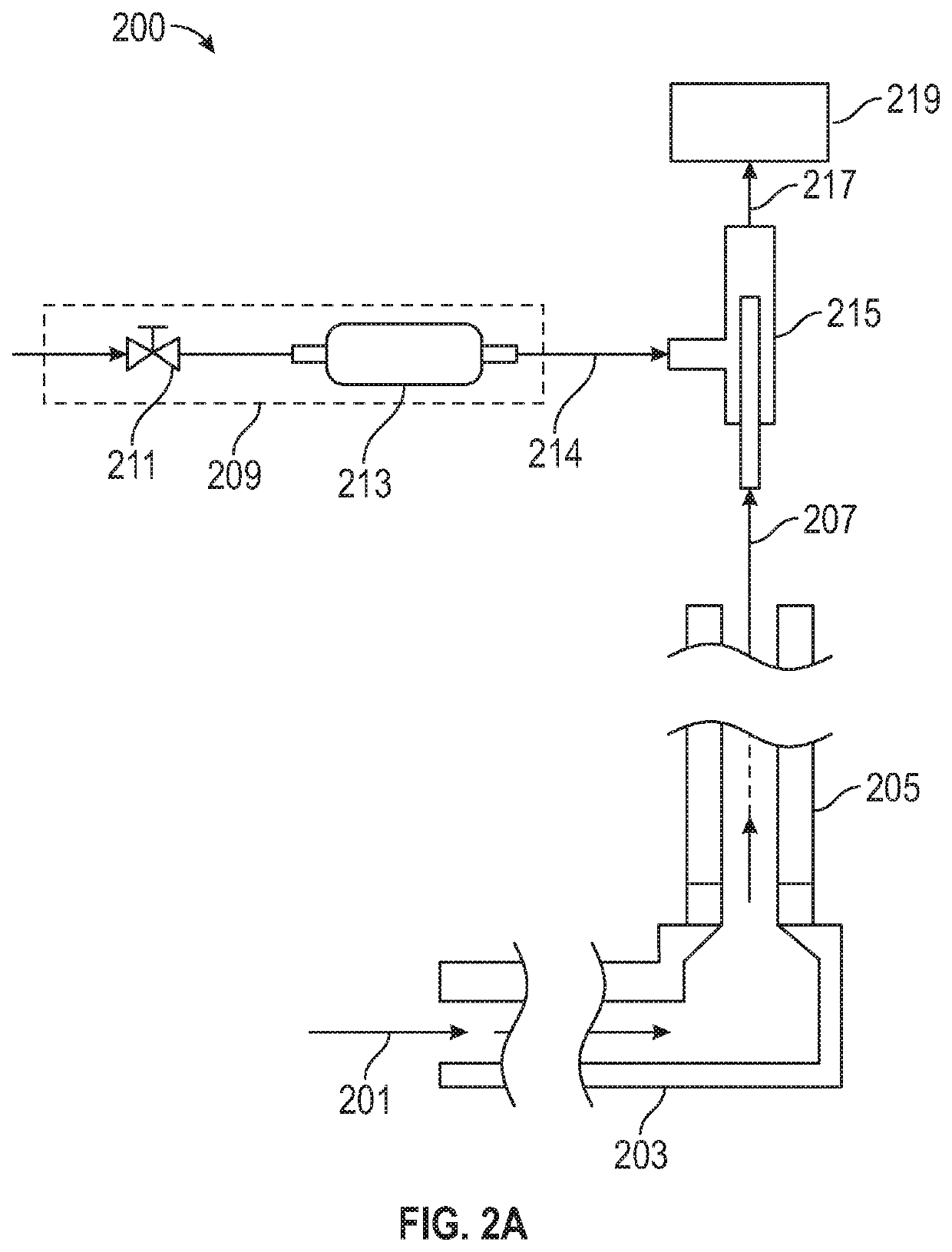
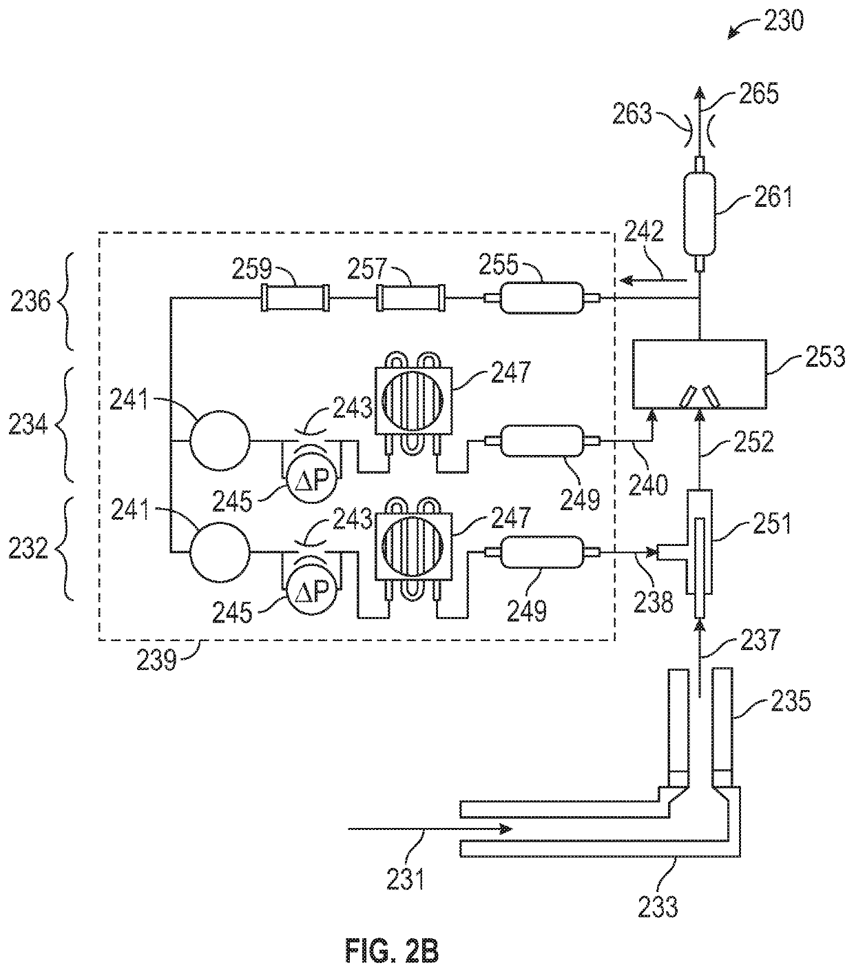
Image

Examples
Embodiment Construction
[0028]The description that follows includes illustrative examples, devices, and apparatuses that embody various aspects of the disclosed subject matter. In the following description, for purposes of explanation, numerous specific details are set forth in order to provide an understanding of various embodiments of the inventive subject matter. It will be evident however, to those of ordinary skill in the art, that various embodiments of the disclosed subject matter may be practiced without these specific details. Further, well-known structures, materials, and techniques have not been shown in detail, so as not to obscure the various illustrated embodiments.
[0029]As used herein, the term “or” may be construed in an inclusive or exclusive sense. Additionally, although various exemplary embodiments discussed below focus on counting particles from high-concentration emission sources, the disclosed subject matter is also related to particle counting and removal of volatile and semi-volati...
PUM
 Abstract
Description
Claims
Application Information
 - R&D Engineer
- R&D Manager
- IP Professional
- Industry Leading Data Capabilities
- Powerful AI technology
- Patent DNA Extraction
Browse by: Latest US Patents, China's latest patents, Technical Efficacy Thesaurus, Application Domain, Technology Topic.
© 2024 PatSnap. All rights reserved.Legal|Privacy policy|Modern Slavery Act Transparency Statement|Sitemap