Backlight module and display device

Active Publication Date: 2021-11-18
WUHAN CHINA STAR OPTOELECTRONICS TECH CO LTD
View PDF0 Cites 0 Cited by
  • Summary
  • Abstract
  • Description
  • Claims
  • Application Information

AI Technical Summary

Benefits of technology

[0022]Compared with the backlight module and the display device of the prior art, the backlight module and the display device of the present invention omit the step of doping the yellow phosphor into the sealant by disposing the first, second, third, and fourth LED chips. The transparent sealant of the present invention redu

Problems solved by technology

However, the single color light emitted by the mini-LED surface light source needs to pas

Method used


Image

  • Backlight module and display device
  • Backlight module and display device

Examples


Embodiment Construction

[0029]Please refer to the figures in the drawings, in which the same reference numerals represent the same components. The following description is based on the specific embodiments of the present invention as illustrated, and should not be construed as limiting the specific embodiments that are not described herein.

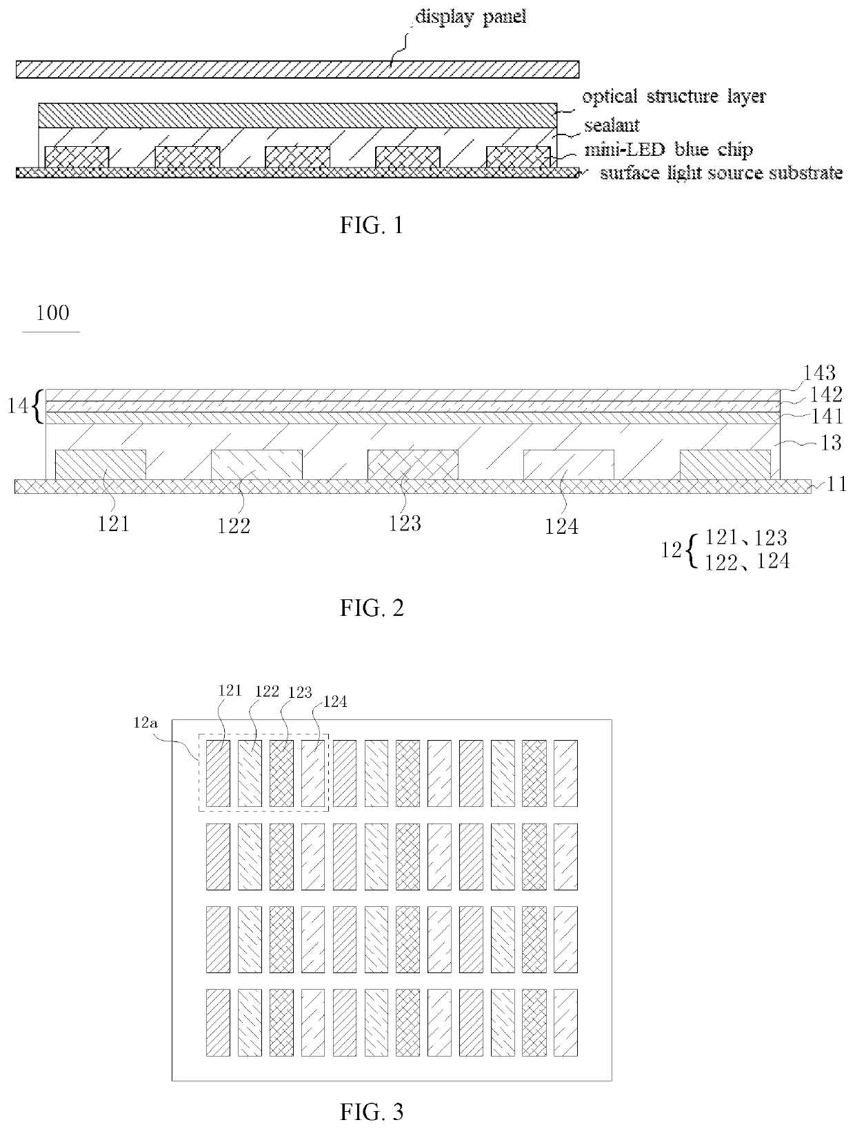
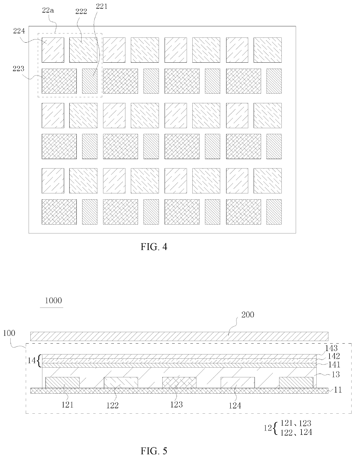
[0030]Referring to FIG. 2 and FIG. 3, FIG. 2 is a schematic structural diagram of a backlight module according to a first embodiment of the present invention, and FIG. 3 is a schematic diagram showing an arrangement structure of mini-light-emitting diode (mini-LED) chips of a backlight module according to a first embodiment of the present invention. The backlight module 100 of the first embodiment includes a substrate 11, mini-light-emitting diode (mini-LED) chips 12, a sealant 13, and an optical module structure 14.

[0031]The mini-LED chip 12 is used for light emission and is disposed on the substrate 11. The mini-LED chips 12 are spaced apart from each other. The mini-L...


PUM


Abstract

The present application provides a backlight module and a display device, wherein mini light-emitting diode (mini-LED) chips disposed on a substrate for light emission, the mini-LED chips being spaced apart from each other and comprising a first LED chip for emitting red light, a second LED chip for emitting green light, a third LED chip for emitting blue light, and a fourth LED chip for emitting yellow light; and wherein a sealant is transparent and disposed on the substrate and covering the mini-LED chips for package; and an optical film structure disposed on the sealant.

Description

BACKGROUND OF INVENTIONField of Invention[0001]The present invention relates to a display technology, and in particular, to a backlight module and a display device.Description of Prior Art[0002]With development of mini-light emitting diode (mini-LED) technology, application fields of a mini-LED surface light source have been broadened, and more and more applications have been proposed.[0003]At present, a basic structure of a display device having the mini-LED surface light source (as shown in FIG. 1) includes a display panel, an optical structure layer, and a mini-LED surface light source, wherein the mini-LED surface light source includes a sealant (containing a yellow phosphor), a mini-LED blue chip, and a surface light source substrate.[0004]However, the single color light emitted by the mini-LED surface light source needs to pass through the yellow phosphor, which forms stray light, resulting in low color saturation.SUMMARY OF INVENTION[0005]An embodiment of the present inventio...

Claims


Application Information

Patent Timeline
IPC IPC(8): F21V8/00
CPCG02B6/0073G02B6/0051G02B6/0068G02F1/133603G09F9/00G02F1/133613G02F1/133614G02F1/133606G02F1/133607G02F1/133621
Inventor XIAO, SHIYUAN
Owner WUHAN CHINA STAR OPTOELECTRONICS TECH CO LTD
Why Eureka
Try Eureka