Coil component and electronic component

Pending Publication Date: 2021-12-02
MURATA MFG CO LTD
View PDF0 Cites 0 Cited by
  • Summary
  • Abstract
  • Description
  • Claims
  • Application Information

AI Technical Summary

Benefits of technology

[0006]Accordingly, the present disclosure provides a coil component that can enhance t

Problems solved by technology

However, only connecting the conductive wire of the coil conductor may fail to bring sufficient

Method used


Image

  • Coil component and electronic component
  • Coil component and electronic component
  • Coil component and electronic component

Examples


Example

First Embodiment

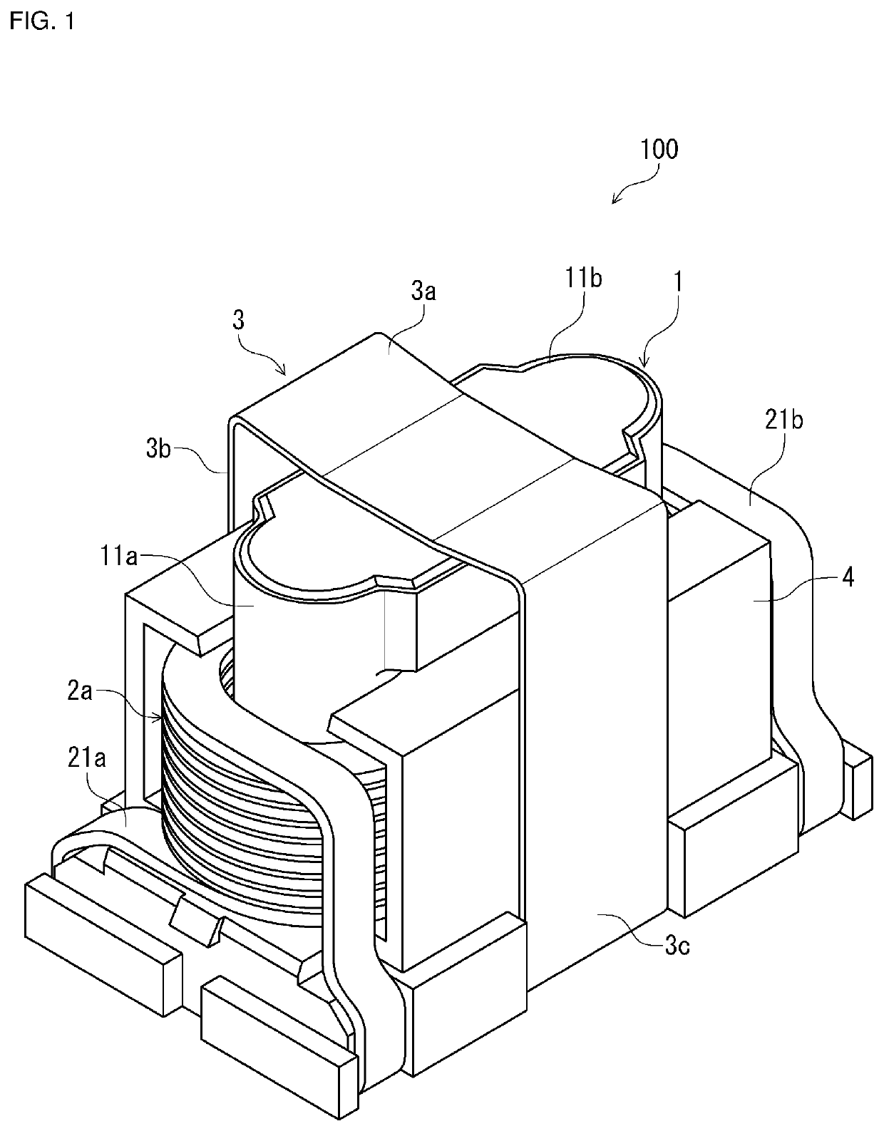
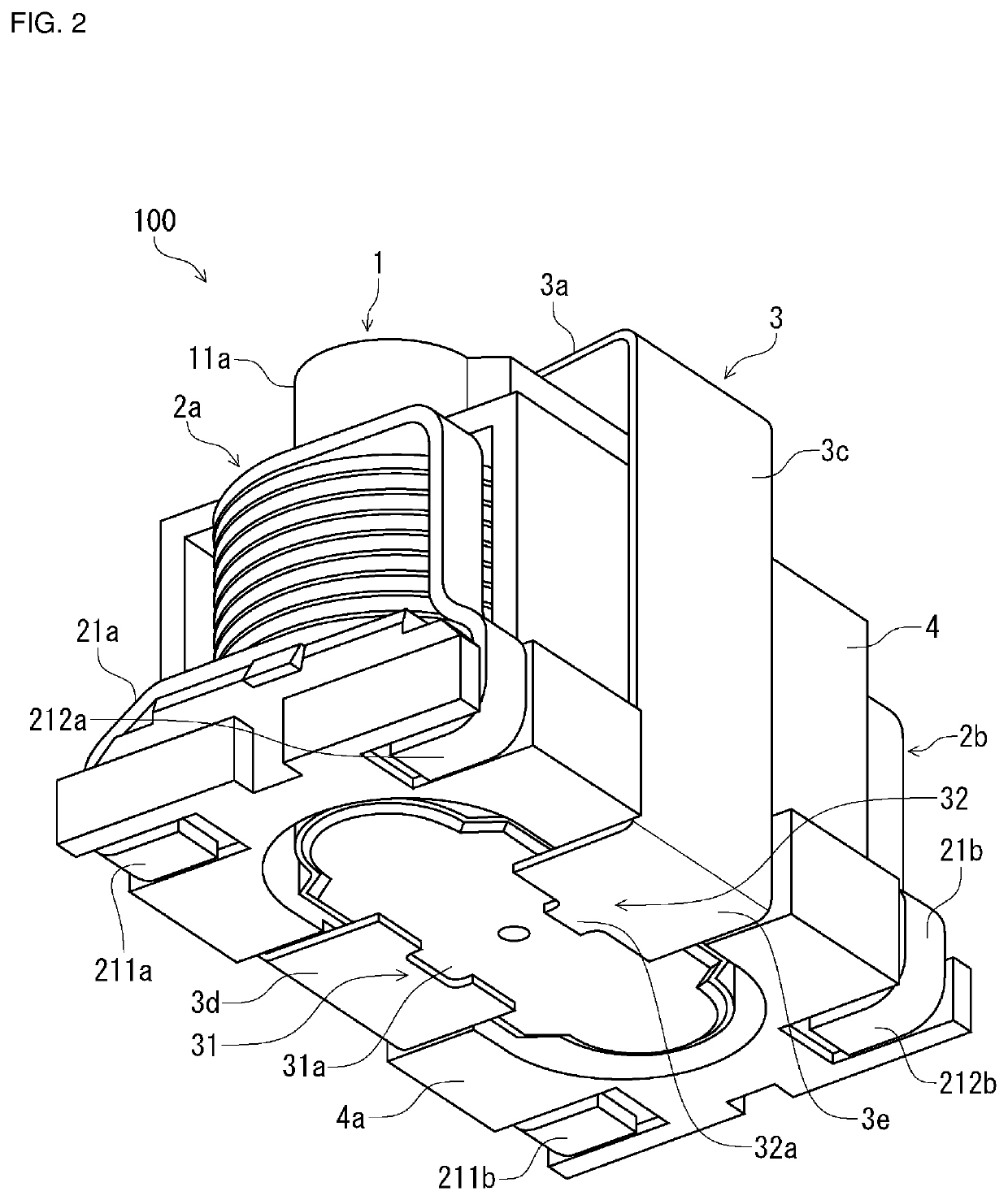
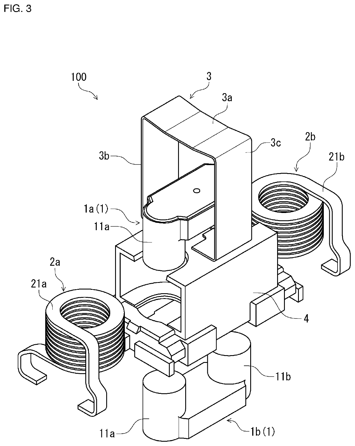
[0023]FIG. 1 is a perspective view that schematically illustrates the shape of a coil component 100 according to a first embodiment, which is viewed from diagonally above. FIG. 2 is a perspective view that schematically illustrates the shape of the coil component 100 according to the first embodiment, which is viewed from diagonally below. FIG. 3 is an exploded perspective view for describing the structure of the coil component 100 according to the first embodiment.

[0024]The coil component 100 according to the first embodiment includes a magnetic core 1, a first coil conductor 2a and a second coil conductor 2b, which constitute a pair of coil conductors, and a securing member 3. The coil component 100 according to the present embodiment further includes a holding member 4.

[0025]As illustrated in FIG. 3, the magnetic core 1 is made up of a first magnetic core 1a and a second magnetic core 1b, which can be separated. That is, the first magnetic core 1 and the second ma...

Example

Second Embodiment

[0055]A coil component 100 according to a second embodiment is different from the coil component 100 according to the first embodiment in the shape of the securing member.

[0056]FIG. 7A is a perspective view that schematically illustrates the shape of a securing member 3A of the coil component 100 according to the second embodiment, which is viewed from diagonally above, and FIG. 7B is a perspective view that schematically illustrates the shape of the securing member 3A, which is viewed from diagonally below.

[0057]Also in the coil component 100 according to the second embodiment, one distal end portion of the securing member 3A, which is one of a first distal end portion 31 of a first bottom surface portion 3d and a second distal end portion 32 of a second bottom surface portion 3e, has a projecting portion that projects toward the other distal end portion while the other distal end portion has a depressed portion, and in the state where the securing member 3A is rem...

Example

Third Embodiment

[0062]A coil component 100 according to a third embodiment is different from the coil components 100 according to the first and second embodiments in the shape of the securing member.

[0063]FIG. 8A is a perspective view that schematically illustrates the shape of a securing member 3B of the coil component 100 according to the third embodiment, which is viewed from diagonally above, and FIG. 8B is a perspective view that schematically illustrates the shape of the securing member 3B, which is viewed from diagonally below.

[0064]Also in the coil component 100 according to the third embodiment, one distal end portion of the securing member 3B, which is one of a first distal end portion 31 of a first bottom surface portion 3d and a second distal end portion 32 of a second bottom surface portion 3e, has a projecting portion that projects toward the other distal end portion while the other distal end portion has a depressed portion, and in the state where the securing member ...


PUM


Abstract

A coil component includes a magnetic core that includes a pair of wind portions, a pair of coil conductors where respective conductive wires are wound around the wind portions, and a securing member that has spring properties, includes an upper surface portion, first and second side surface portions, and first and second bottom surface portions, and secures the core while surrounding the core. With the securing member removed from the core, angles formed by the upper surface portion and first side surface portion, the upper surface portion and second side surface portion, the first side surface portion and first bottom surface portion, and the second side surface portion and second bottom surface portion are acute angles. The first and second side surface portions are formed by curved surfaces. The first and second bottom surface portions serve as mounted portions when the coil component is mounted over a mounting board.

Description

CROSS-REFERENCE TO RELATED APPLICATION[0001]This application claims benefit of priority to Japanese Patent Application No. 2020-091921, filed May 27, 2020, the entire content of which is incorporated herein by reference.BACKGROUNDTechnical Field[0002]The present disclosure relates to a coil component and an electronic component where the coil component is provided.Background Art[0003]A coil component having a structure in which a conductive wire is wound around a wind portion of a magnetic core is known. It is also known to secure a magnetic core and a coil conductor where a conductive wire is wound using a securing member having spring properties.[0004]Japanese Unexamined Patent Application Publication No. 7-106157 describes how a combination structure of a transformer core and a bobbin (coil conductor) is secured by a flat spring surrounding the combination structure.[0005]When a coil component is mounted over a mounting board, the coil component is typically mounted using solder ...

Claims


Application Information

Patent Timeline
IPC IPC(8): H01F27/26H01F27/28
CPCH01F27/266H01F27/2823H01F27/06H01F17/04H01F2027/065H01F27/306H01F27/263H01F27/2852
Inventor MAKI, KENICHIRO
Owner MURATA MFG CO LTD
Why Eureka
Try Eureka