
Optimization method for capacity of heat pump and power of various sets of energy source equipment in energy hub

a technology of energy hub and heat pump, which is applied in the field of energy hubs, can solve the problems of large optimization difficulties, large or small heat pump capacity, and the inability of modern society to survive and develop without support, and achieve the effect of avoiding complicated analysis of mathematical models

Pending Publication Date: 2021-12-02
XIANGTAN UNIV
View PDF6 Cites 7 Cited by
  • Summary
  • Abstract
  • Description
  • Claims
  • Application Information

AI Technical Summary

Benefits of technology

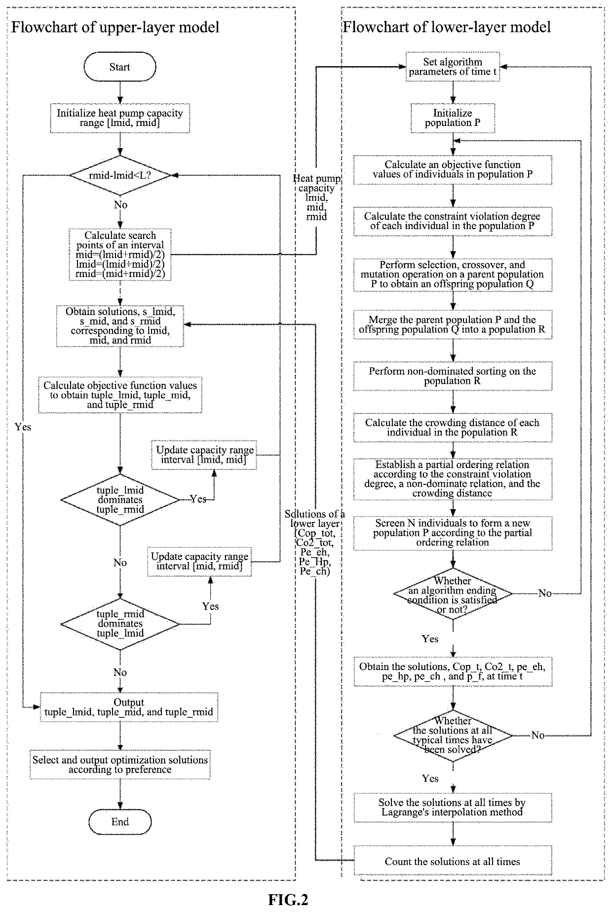
The patent text describes an optimization method for the capacity of a heat pump and the power of various sets of energy source equipment in an energy hub. The method uses a double-layer optimization model with an improved binary search algorithm in the upper layer and an improved multi-objective evolutionary algorithm NSGA-II in the lower layer. The two layers of models are optimized independently, and the results are integrated to obtain optimal solutions. The method simplifies the analysis of the problem and avoids complicated analysis of a mathematical model, allowing for direct optimization of the original problem. The technical effect of this patent is to provide a more efficient and effective optimization method for energy hubs, reducing costs and emissions.

Problems solved by technology

Modern society cannot survive and develop without the support of energy sources.
Optimizing the capacity of equipment and the power of various sets of the energy source equipment in the energy hub on the premise of satisfying the needs of the cooling and heating load and a variety of constraints is a problem to be optimized by the present disclosure.
The problem has nonlinear stochastic characteristics, which brings great difficulties to optimization.
In the energy hub, the power of various sets of equipment can be optimized only after the capacity of the various sets of equipment is set, which is obviously a problem about master-slave optimization.
(4-3) According to the analysis of a heat pump efficiency graph, large or small heat pump capacity is not beneficial to the operation of the whole energy hub.

Method used


Image

  • Optimization method for capacity of heat pump and power of various sets of energy source equipment in energy hub
  • Optimization method for capacity of heat pump and power of various sets of energy source equipment in energy hub
  • Optimization method for capacity of heat pump and power of various sets of energy source equipment in energy hub

Examples


embodiment 1

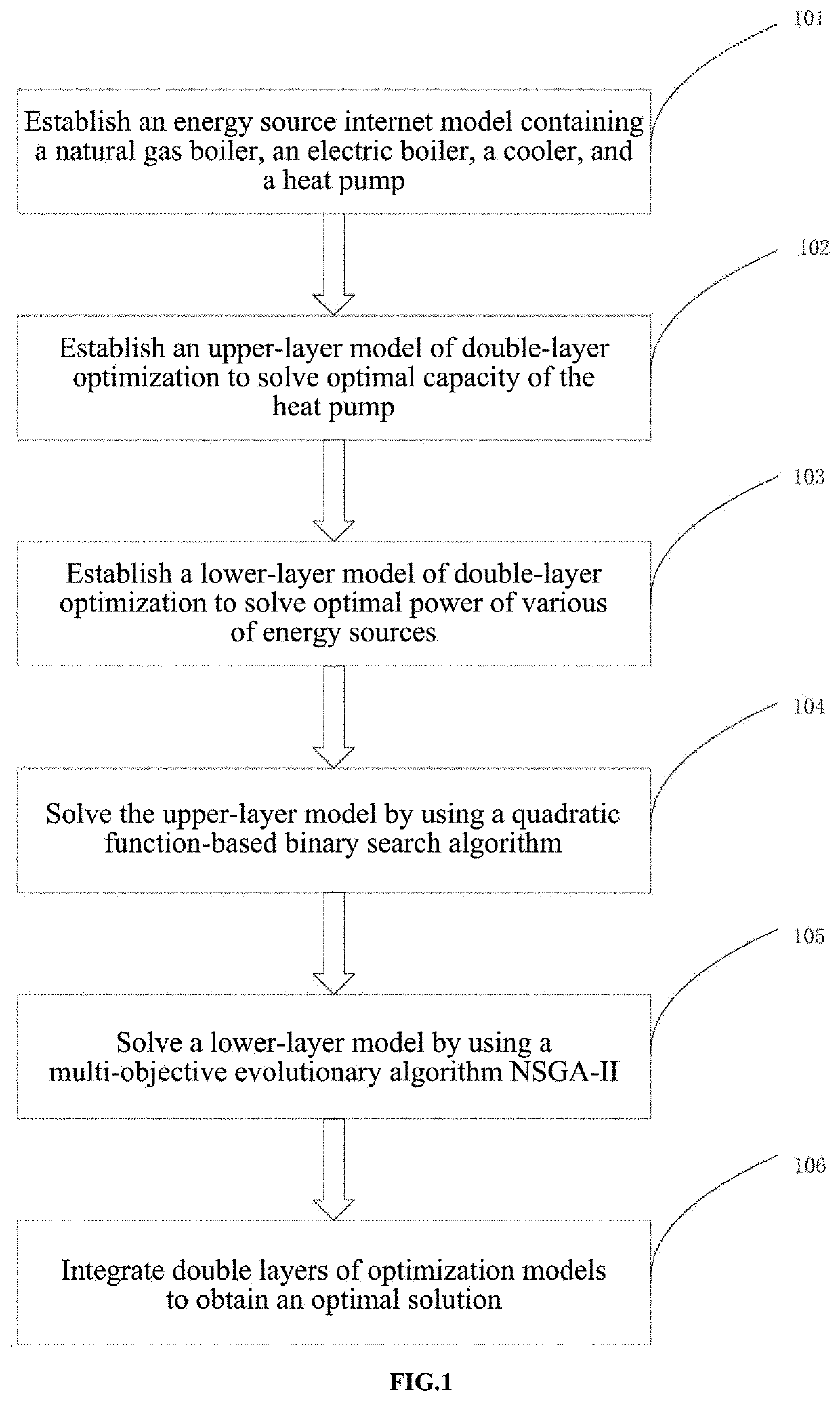
[0081]FIG. 2 is a flowchart of an optimization method for capacity of a heat pump and power of various sets of energy source equipment in an energy hub of the embodiments of the present disclosure. The method includes:

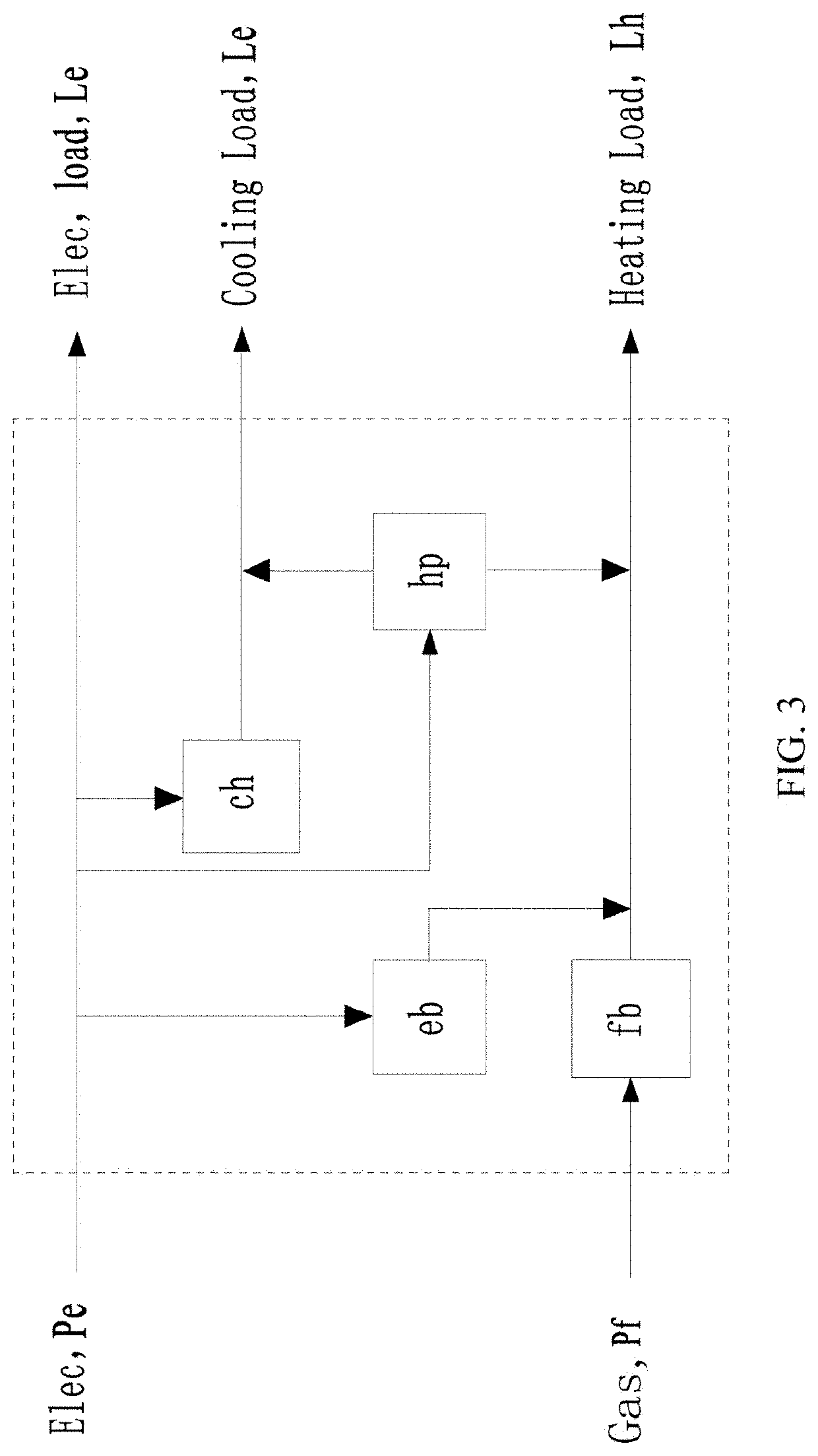
[0082](1) establishing an energy hub model containing a natural gas boiler, an electric boiler, a cooler, and a heat pump;

[0083](2) establishing an upper-layer model of double-layer optimization to solve optimal capacity of the heat pump;

[0084](3) establishing a lower-layer model of double-layer optimization to solve optimal power of the various sets of energy source equipment;

[0085](4) solving the upper-layer model by using a quadratic function-based binary search algorithm;

[0086](5) solving a lower-layer model by using a multi-objective evolutionary algorithm NSGA-II;

[0087](6) integrating double layers of optimization models to obtain an optimal solution.

[0088]Optionally, the energy source equipment includes a natural gas boiler, an electric boiler, a cooler, and a h...


PUM


Abstract

The present disclosure discloses a method for optimizing equipment capacity and equipment power of an energy hub system. The method includes establishing an energy hub model containing natural gas boilers, electric boilers, coolers and heat pumps, establishing a bilevel optimized upper model to solve the optimal heat pump capacity, and establishing a bilevel optimized lower model to solve the optimal power utilization of each energy device based on the binary search algorithm of the quadratic function solves the upper model by using the multi-objective evolutionary algorithm NSGA-II to solve the lower model. The optimization method of the present invention can solve the multi-objective bilevel model problem without the help of commercial optimization software. Obtaining a reasonable, efficient and green planning scheme makes the total operating cost and total exhaust gas emissions of the energy hub relatively optimal.

Description

CROSS REFERENCE TO RELATED APPLICATION(S)[0001]This patent application claims the benefit and priority of Chinese Patent Application No. 202010471573.8, filed on May 28, 2020, the disclosure of which is incorporated by reference herein in its entirety as part of the present application.TECHNICAL FIELD[0002]The present disclosure relates to the field of energy hubs, and in particular, to an optimization method for capacity of a heat pump and power of various sets of energy source equipment in an energy hub.BACKGROUND ART[0003]Modern society cannot survive and develop without the support of energy sources. With the development and progress of society, the demand for the energy sources is increasing. At present, the main energy source is still traditional fossil energy source. With the occurrences of the problems of deteriorating environment and the like caused by gradual depletion of the traditional fossil energy source and energy consumption, various countries are actively studying r...

Claims


Application Information

Patent Timeline
Patent Type & Authority Applications(United States)
IPC IPC(8): H02J3/00H02J3/28
CPCH02J3/003H02J3/004H02J3/28G06F30/20G06Q10/04G06Q50/06G06F2119/08G06F30/17G06F2113/08
Inventor ZOU, JUANYANG, XUPEI, TINGRUIZHENG, JINHUALIU, ZHONGBING
Owner XIANGTAN UNIV
Learn More