Straight spur gear finite element mesh automatic generation method based on tooth profile and computer equipment

A spur gear, automatic generation technology, applied in design optimization/simulation, geometric CAD and other directions, can solve the problems of low work efficiency and low grid node accuracy, and achieve the effect of improving efficiency and low computational complexity

Active Publication Date: 2022-07-29
HARBIN ENG UNIV
View PDF19 Cites 0 Cited by
  • Summary
  • Abstract
  • Description
  • Claims
  • Application Information

AI Technical Summary

Problems solved by technology

[0004] The purpose of the present invention is to solve the problems of low accuracy and low work efficiency of grid nodes obtained by existing methods, and to provide a method and computer equipment for automatically generating finite element grids of spur gears based on tooth profiles

Method used


Image

  • Straight spur gear finite element mesh automatic generation method based on tooth profile and computer equipment
  • Straight spur gear finite element mesh automatic generation method based on tooth profile and computer equipment
  • Straight spur gear finite element mesh automatic generation method based on tooth profile and computer equipment

Examples


Embodiment approach 1

[0096] Embodiment 1. A method for automatically generating finite element meshes of spur gears based on tooth profile, the method comprising:

[0097] Step 1. Take the symmetry axis of a gear tooth section in the spur gear as the y-axis, and take the straight line passing through the center of the gear circle and perpendicular to the y-axis as the x-axis to establish a Cartesian coordinate system;

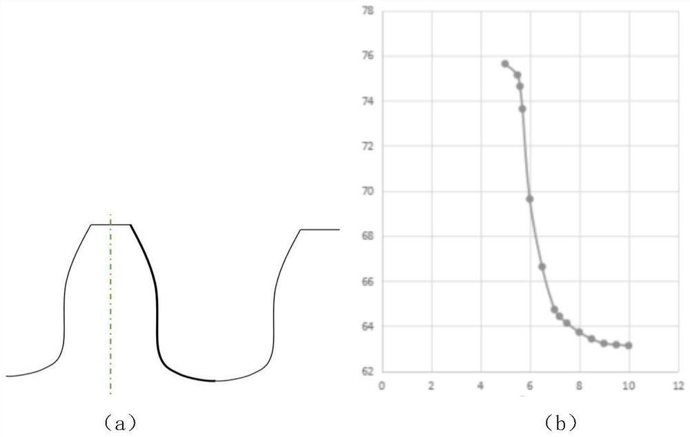
[0098] Step 2. Under the Cartesian coordinate system, obtain the tooth profile of half a gear tooth, and the tooth profile takes the intersection of the tooth profile and the tip circle as the starting point, and takes the tooth root profile point as the end point;

[0099] Step 3. According to the tooth profile, the inner circle radius of the gear and the boundary line of the gear teeth, establish a half gear tooth frame;

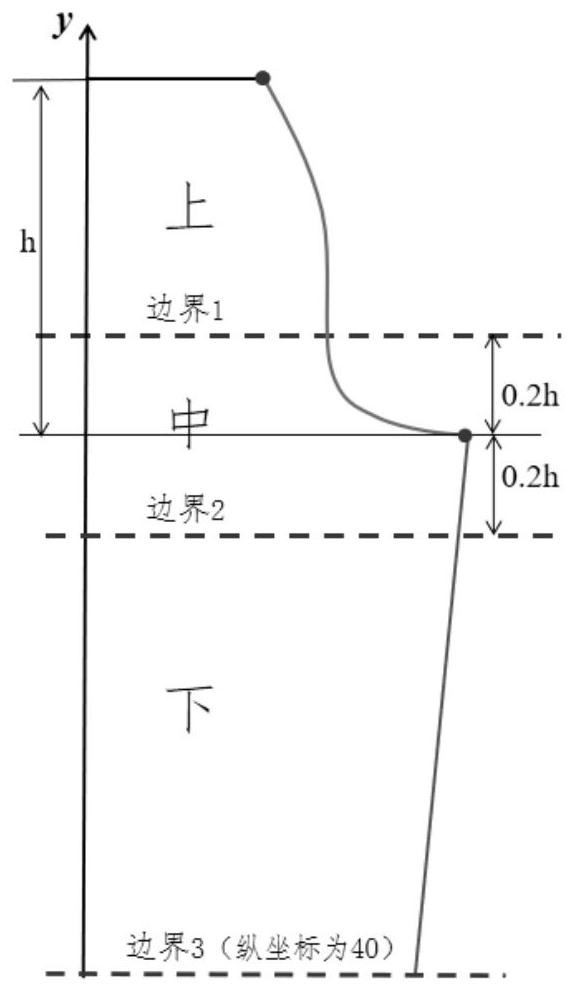
[0100] Step 4. Divide the half gear tooth frame into an upper area, a middle area and a lower area, wherein the upper area corresponds to the gear teeth part, ...

Embodiment approach 2

[0109] Embodiment 2, this embodiment is a further limitation of the method for automatically generating finite element meshes of spur gears based on tooth profile described in Embodiment 1. In this embodiment, the step 4 is done. Further limited, specifically including:

[0110] Step 4.1. Obtain the difference between the ordinates of the starting point and the ending point;

[0111] Step 4.2, set a preset ratio, and determine the difference between the ordinate of the boundary line and the ordinate of the end point according to the difference between the ordinates and the opportunity of the preset ratio;

[0112] Step 4.3, according to the difference between the ordinate of the boundary line and the ordinate of the end point, obtain the boundary line of the half-gear frame at the upper and lower azimuths of the end point;

[0113] Step 4.4, according to the boundary line, divide the half-gear frame into an upper area, a middle area and a lower area.

[0114] In this embodim...

Embodiment approach 3

[0115] Embodiment 3, this embodiment is a further limitation of the method for automatically generating finite element meshes of spur gears based on tooth profile described in Embodiment 1. In this embodiment, the step 5 is done. Further limited, specifically including:

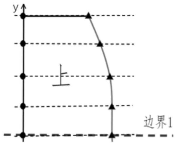
[0116] Step 5.1, for the upper area, set the upper vertical fraction parameter and the upper horizontal fraction parameter, and perform grid division on the upper area according to the upper vertical fraction parameter and the upper horizontal fraction parameter to obtain the upper All nodes in the area, all the nodes in the upper area include nodes on the boundary line between the upper area and the middle area;

[0117] Step 5.2, for the middle area, set the middle vertical share parameter, according to the middle vertical share parameter, the upper horizontal share parameter and the node on the boundary line between the upper area and the middle area, and Use quadratic Bezier curve to mesh the middle regi...


PUM


Abstract

The invention discloses a tooth profile-based straight spur gear finite element mesh automatic generation method and computer equipment, belongs to the technical field of gear simulation, and solves the problems of low mesh node precision and low working efficiency of an existing method. The method comprises the following steps: establishing a rectangular coordinate system; acquiring a tooth profile of a half gear tooth; according to the tooth profile line, the gear inner circle radius and the gear tooth boundary line, a half gear tooth frame is established; the half gear tooth frame is divided into an upper area, a middle area and a lower area; performing grid division on the upper region, the middle region and the lower region to obtain all nodes of a half gear tooth section; obtaining all nodes of a single gear tooth according to all nodes of the half gear tooth section; according to all the nodes of the single gear tooth, all the nodes of the whole gear are obtained; and compiling a connection relationship, and obtaining a gear grid model. The method is suitable for automatic generation of the straight spur gear finite element mesh model.

Description

technical field [0001] The present application relates to the technical field of gear simulation, and in particular, to a method and computer equipment for automatically generating finite element meshes of spur gears based on tooth profiles. Background technique [0002] As an important form of mechanical transmission, spur gear transmission is widely used in the power transmission of automobiles, rail vehicles and other transportation vehicles, and mechanical equipment for production and life. During the rotation of the gears, loads are transferred between the gears. When the rotation speed is fast and the load is large, imprints will be left on the gears, and even the gears will be worn or even broken. In order to minimize the damage of these gears, simulation analysis of the gears is required, and meshing of the gears is an essential step. [0003] In the prior art, in the gear finite element analysis: on the one hand, gear mesh division needs to first establish a three...

Claims


Application Information

Patent Timeline
Patent Type & Authority Applications(China)
IPC IPC(8): G06F30/17G06F30/23
CPCG06F30/17G06F30/23Y02T90/00
Inventor 唐滨刘昊康李宝君黄礼敏
Owner HARBIN ENG UNIV
Why Eureka
Try Eureka