Supercharge Your Innovation With Domain-Expert AI Agents!

Machining center and workpiece processing method

a technology of workpiece processing and machining center, which is applied in the direction of computer control, program control, instruments, etc., can solve the problems of affecting machining accuracy and long machining time, and achieve the effect of higher speeds

Pending Publication Date: 2021-12-09
MAKINO MILLING MASCH CO LTD
View PDF0 Cites 1 Cited by
  • Summary
  • Abstract
  • Description
  • Claims
  • Application Information

AI Technical Summary

Benefits of technology

The present patent is about a machining center and a workpiece machining method that can correct parallelism errors between the Z-axis and the W-axis, which can affect machining accuracy. The center has Y-axis and B-axis drive devices that can move the spindle head and table, respectively, to correct the parallelism error. This allows for faster machining of workpieces and higher accuracy in the finished product.

Problems solved by technology

However, for example, when forming a deep hole in the workpiece, a long feed is required, whereby a long machining time is necessary.
In the machining center according to the aspect of the present disclosure, since the feeding between the workpiece and the tool is achieved by both movement along the Z-axis and movement along the W-axis, parallelism errors between the Z-axis and the W-axis can affect machining accuracy.

Method used


Image

  • Machining center and workpiece processing method
  • Machining center and workpiece processing method
  • Machining center and workpiece processing method

Examples


Embodiment Construction

[0023]The machining center and workpiece machining method according to an embodiment will be described below with reference to the attached drawings. Identical or corresponding elements have been assigned the same reference sign, and duplicate descriptions thereof have been omitted. In order to facilitate understanding, the scales of the drawings have been changed in some cases, and the constituent elements shown in some drawings may be omitted in other drawings.

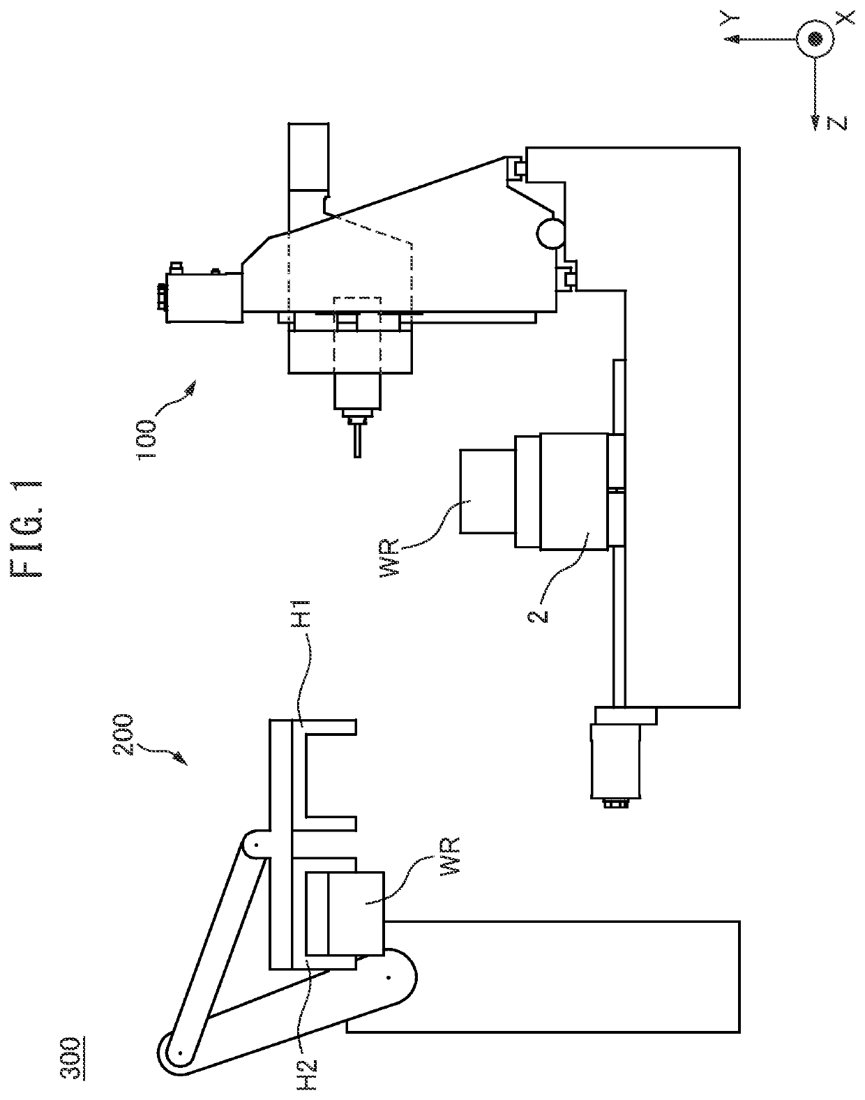
[0024]FIG. 1 is a schematic side view showing a system 300 comprising a machining center 100 according to an embodiment. The system 300 may include, for example, the machining center 100 and a robot 200. The system 300 may further comprise other components. In the system 300, for example, the robot 200 can move along a predetermined path (not illustrated) and a plurality of machining devices including the machining center 100 can be arranged along the path of the robot 200. Note that in FIG. 1, for clarity, only one machinin...


PUM

PropertyMeasurementUnit
of rotationaaaaaaaaaa
rotationaaaaaaaaaa
diameteraaaaaaaaaa

Abstract

A machining center is provided with: a base; a table that supports a workpiece; a main-shaft head that causes a tool to rotate around an axis of rotation of a main-shaft; a Z-axis drive device that causes the table to move with respect to the base along a Z axis parallel to the axis of rotation of the main-shaft; a W-axis drive device that causes the main-shaft head to move with respect to the base along a W axis parallel to the axis of rotation of the main-shaft; and a control device that controls the Z-axis drive device and the W-axis drive device so as to cause the tool to process the workpiece by causing the table and the main-shaft head to move along the Z axis and the W axis, respectively.

Description

[0001]This application is a US National Stage Application under 35 USC 371 of International Patent Application No. PCT / JP2018 / 040181, filed Oct. 29, 2018, the entire contents of which is incorporated herein by reference.FIELD OF THE DISCLOSURE[0002]The present disclosure relates to a machining center and a workpiece machining method.BACKGROUND OF THE DISCLOSURE[0003]Machining centers rotate a tool, and can machine a workpiece while moving the tool and the workpiece relative to each other in a direction parallel to the axis of rotation of the tool (for example, hole drilling, etc.). For example, Patent Literature 1 discloses a five-axis composite machine tool capable of holding two tools, i.e., a tool for machining large diameter holes and a tool for machining small diameter holes. In this machine tool, a cutter holder moves in the vertical direction on a cutter holder guide. The cutter holder comprises a tool mounting part. The tool mounting part holds the tool for machining large d...

Claims


Application Information

Patent Timeline
Patent Type & Authority Applications(United States)
IPC IPC(8): B23Q1/58B23B35/00G05B19/402
CPCB23Q1/58G05B2219/35519G05B19/402B23B35/00G05B19/404B23Q1/626B23Q7/048B23Q17/22G05B2219/50142
Inventor SANO, YUJI
Owner MAKINO MILLING MASCH CO LTD
Features
  • R&D
  • Intellectual Property
  • Life Sciences
  • Materials
  • Tech Scout
  • Unparalleled Data Quality
  • Higher Quality Content
  • 60% Fewer Hallucinations
Learn More