Systems and methods for palletization miniaturization and demonstration

a palletization and miniaturization technology, applied in the field of palletization, can solve the problems of time and effort, the robots themselves are a large expense, so as to reduce overhead burden or expense, and be more economical or practical

Inactive Publication Date: 2021-12-09
ASSOC PACKAGING
View PDF0 Cites 1 Cited by
  • Summary
  • Abstract
  • Description
  • Claims
  • Application Information

AI Technical Summary

Benefits of technology

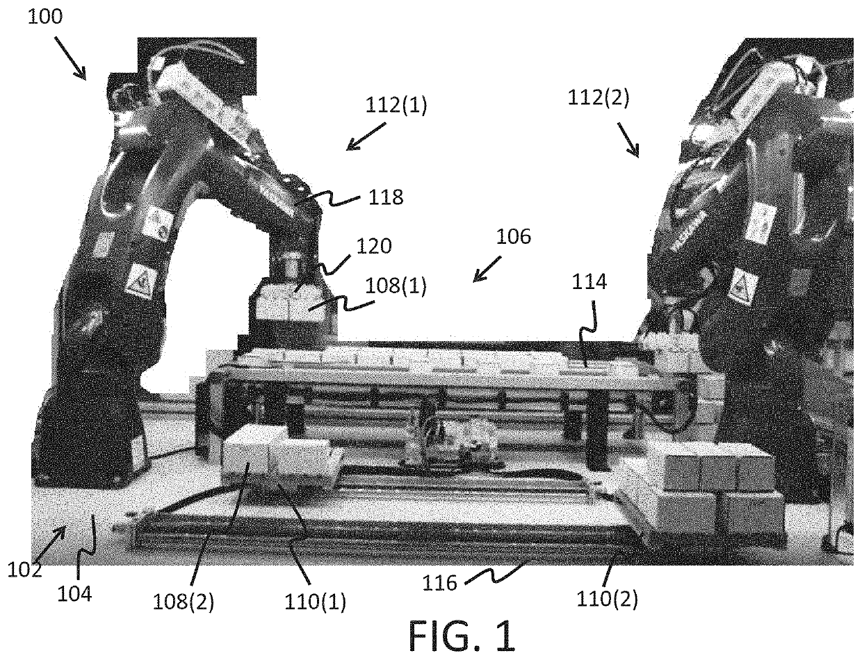
[0011]In some embodiments, the apparatuses, systems, and methods disclosed herein may provide a demonstration of a specific configuration of robotic palletization. A demonstration may show proof of concept that the specific configuration of robot palletization is possible, efficient, or otherwise desirable before attempting to implement the full-scale robotic palletization solution. Providing the robotic palletization scale model may reduce overhead burden or expense or may provide a solution before a full-scale location is available. The scale model may be transported or filmed in order to demonstrate the configuration to a variety of potential customers. A demonstration may assist with training or educational purposes. The demonstration of the palletization process with a miniaturized palletization system may be more economical or practical before attempting to implement the full-scale robotic palletization solution. Numerous other objects, advantages and features of the present disclosure will be readily apparent to those of skill in the art upon a review of the following drawings and description of a preferred embodiment.

Problems solved by technology

However, robotic palletization is very expensive.
The robots themselves are a large expense, and moving them around a factory floor takes time and effort.
However, planning out a palletization configuration with the positions of the various components can be difficult.
Even if a configuration is planned, it is difficult to determine if the configuration will work as planned without actually implementing the configuration.

Method used


Image

  • Systems and methods for palletization miniaturization and demonstration
  • Systems and methods for palletization miniaturization and demonstration
  • Systems and methods for palletization miniaturization and demonstration

Examples


Embodiment Construction

[0028]While the making and using of various embodiments of the present invention are discussed in detail below, it should be appreciated that the present invention provides many applicable inventive concepts that are embodied in a wide variety of specific contexts. The specific embodiments discussed herein are merely illustrative of specific ways to make and use the invention and do not delimit the scope of the invention. Those of ordinary skill in the art will recognize numerous equivalents to the specific apparatus and methods described herein. Such equivalents are considered to be within the scope of this invention and are covered by the claims.

[0029]In the drawings, not all reference numbers are included in each drawing, for the sake of clarity. In addition, positional terms such as “upper,”“lower,”“side,”“top,”“bottom,” etc. refer to the apparatus when in the orientation shown in the drawing. A person of skill in the art will recognize that the apparatus can assume different or...


PUM


Abstract

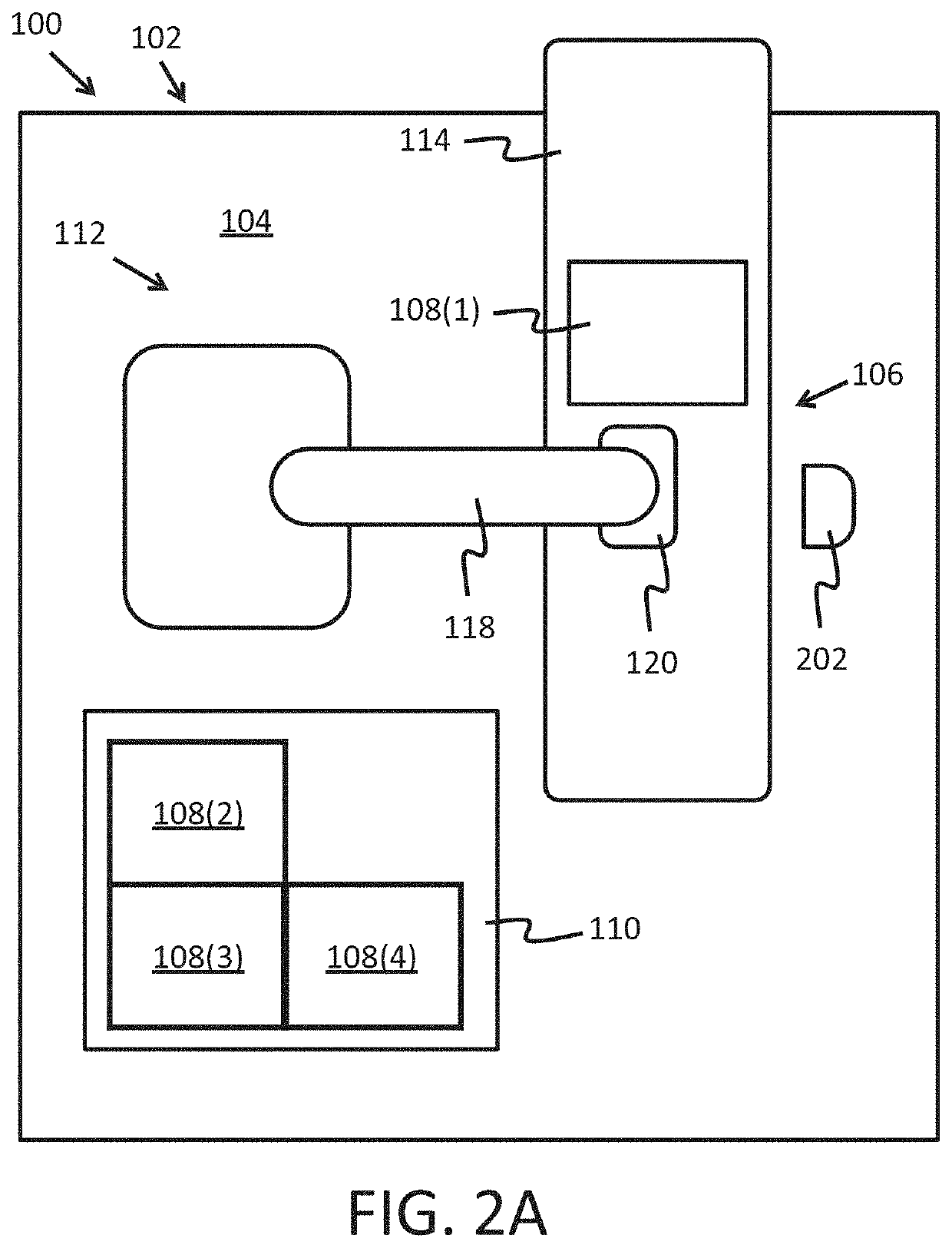
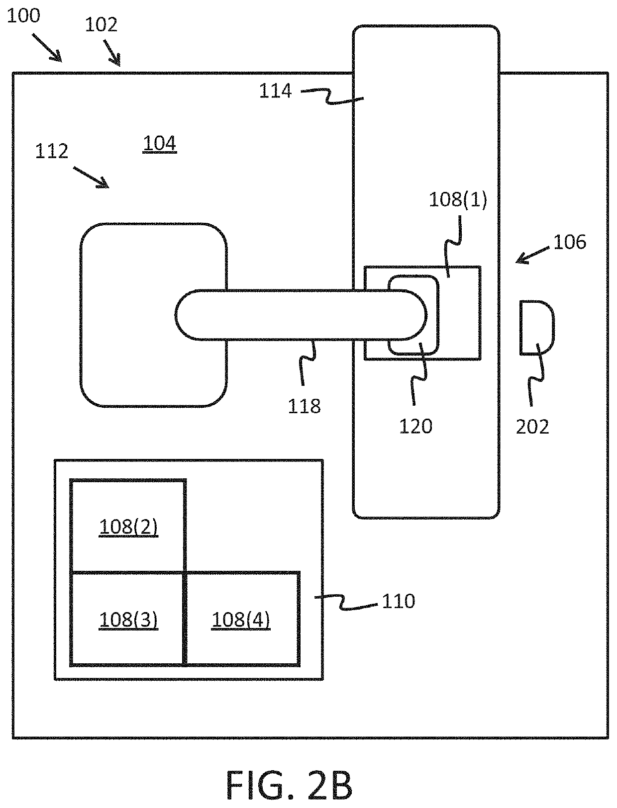
An apparatus for palletization miniaturization and demonstration may include a miniaturized palletization surface that may include a horizontal surface, a miniaturized conveyor disposed on the horizontal surface, a miniaturized material mass, a miniaturized pallet disposed on the horizontal surface, and a miniaturized articulated robot disposed on the horizontal surface, the miniaturized articulated robot including an arm section and an end effector. The miniaturized pallet may be disposed within a reach of the arm section of the miniaturized articulated robot. The miniaturized articulated robot may be operable to grasp, via the end effector, the miniaturized material mass and translate the miniaturized material mass in a horizontal plane, a vertical plane, and a depth plane.

Description

[0001]A portion of the disclosure of this patent document contains material that is subject to copyright protection. The copyright owner has no objection to the reproduction of the patent document or the patent disclosure, as it appears in the U.S. Patent and Trademark Office patent file or records, but otherwise reserves all copyright rights whatsoever.CROSS-REFERENCES TO RELATED APPLICATIONS[0002]Not ApplicableSTATEMENT REGARDING FEDERALLY SPONSORED RESEARCH OR DEVELOPMENT[0003]Not ApplicableREFERENCE TO SEQUENCE LISTING OR COMPUTER PROGRAM LISTING APPENDIX[0004]Not ApplicableBACKGROUND OF THE INVENTION[0005]The present disclosure relates generally to palletization and more particularly to systems and methods for palletization miniaturization and demonstration.[0006]Palletization with robotics, i.e., the loading of a pallet with various loads using a robot, is common in manufacturing. However, robotic palletization is very expensive. The robots themselves are a large expense, and ...

Claims


Application Information

Patent Timeline
Patent Type & Authority Applications(United States)
IPC IPC(8): B65G61/00B25J9/16B25J9/00B25J11/00
CPCB65G61/00B25J9/1628B25J15/06B25J11/005B25J9/0093B33Y80/00B65G57/00B33Y30/00
Inventor MILLER, KEVIN LEE
Owner ASSOC PACKAGING
Why Eureka
Try Eureka