
Micromechanical structure, micromechanical system and method of providing a micromechanical structure

Pending Publication Date: 2021-12-09
FRAUNHOFER GESELLSCHAFT ZUR FOERDERUNG DER ANGEWANDTEN FORSCHUNG EV
View PDF0 Cites 0 Cited by
  • Summary
  • Abstract
  • Description
  • Claims
  • Application Information

AI Technical Summary

Benefits of technology

The patent describes an invention that allows for the easy manufacturing and controlled operation of MEMS devices. The invention uses a transmission arrangement that allows for high precision and reliable control of the actuator force, regardless of its position or deflection angle. This allows for the actuator to operate in a reference plane and move the movable element out of the reference plane using the transmission structure, resulting in high accuracy and reliability of the control.

Problems solved by technology

Applying a static electric voltage results in deflection.
All of the above methods entail a number of technical problems, most notably the technologically complex production of multiple functional planes to operate the devices.

Method used


Image

  • Micromechanical structure, micromechanical system and method of providing a micromechanical structure
  • Micromechanical structure, micromechanical system and method of providing a micromechanical structure
  • Micromechanical structure, micromechanical system and method of providing a micromechanical structure

Examples


Embodiment Construction

[0061]Before embodiments of the present invention are explained in detail below with reference to the drawings, it is pointed out that identical elements, objects and / or structures or those of equal function or equal effect are provided with the same reference signs in the different figures so that the description of these elements shown in different embodiments is interchangeable or mutually applicable.

[0062]The following embodiments relate to micromechanical structures (MMS) comprising an actuator. The actuator may be formed electrically or non-electrically, for example as a thermal actuator. If the actuator is formed as an electrical actuator, for example an electrostatic actuator, piezoelectric actuator, pneumatic actuator, and / or hydraulic actuator, the MMS may also be referred to as a micro-electro-mechanical system (MEMS). The terms MMS and MEMS used herein are therefore combinable or interchangeable as desired and are used as synonyms unless specific differences are discusse...


PUM


Abstract

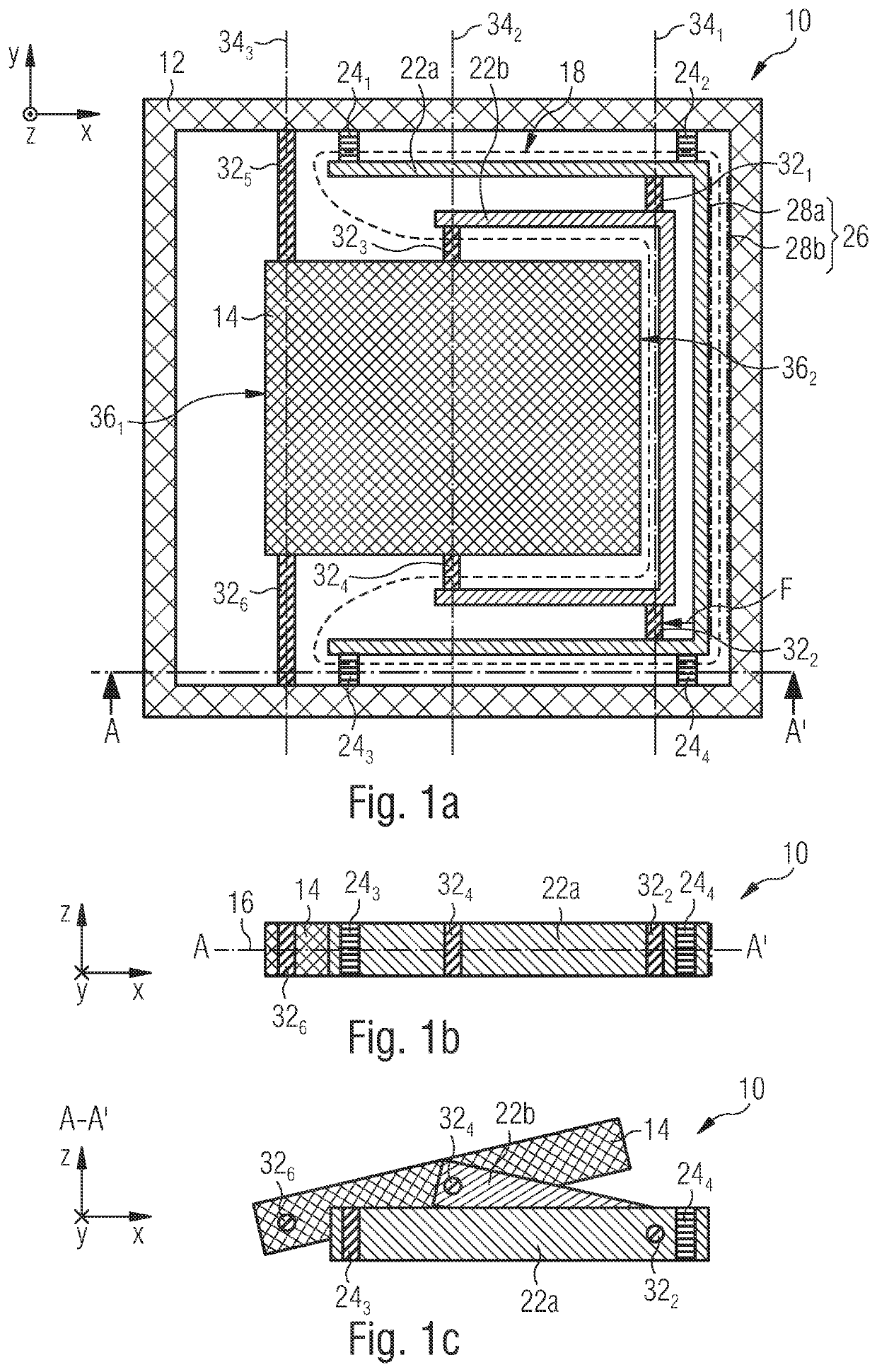
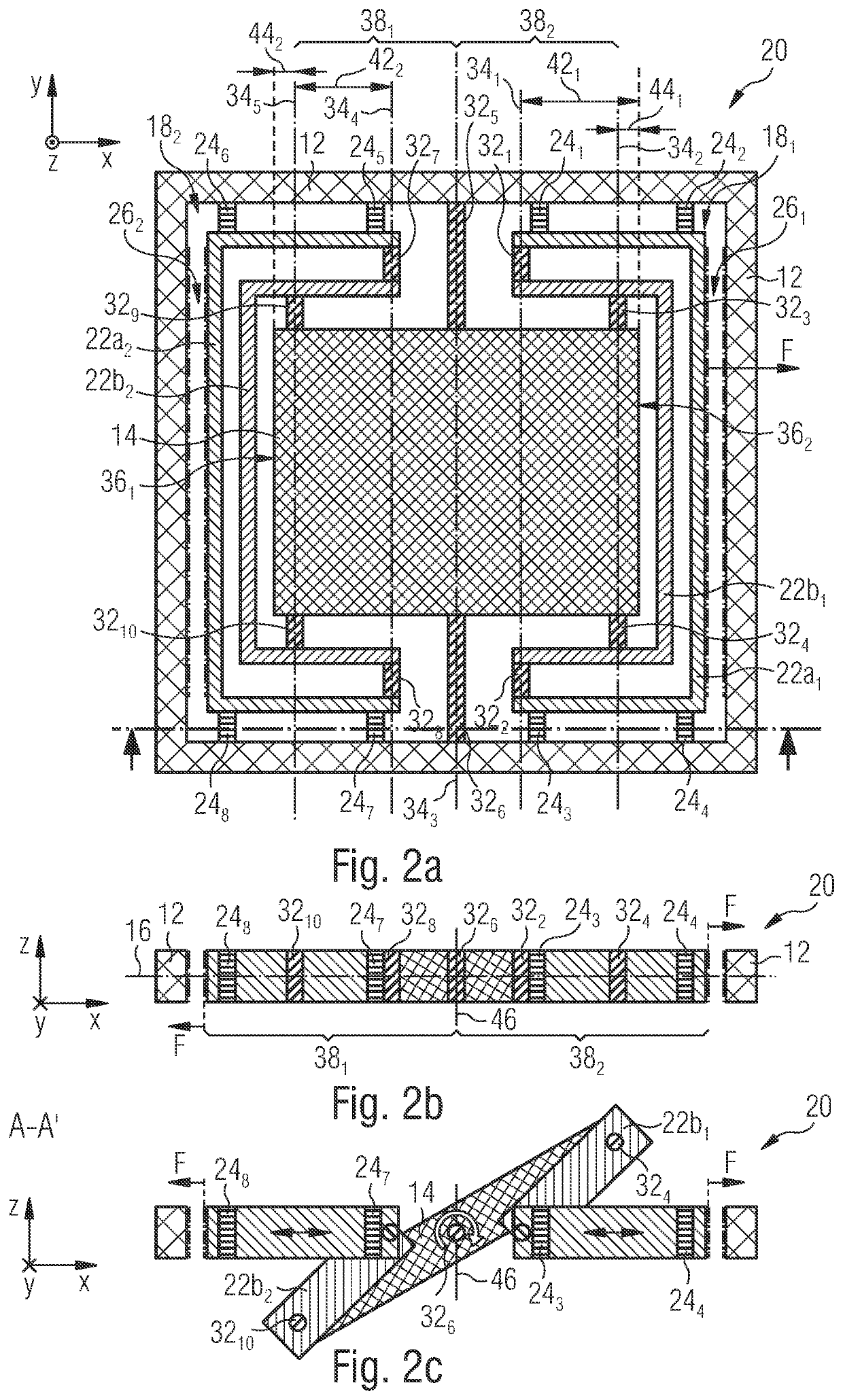
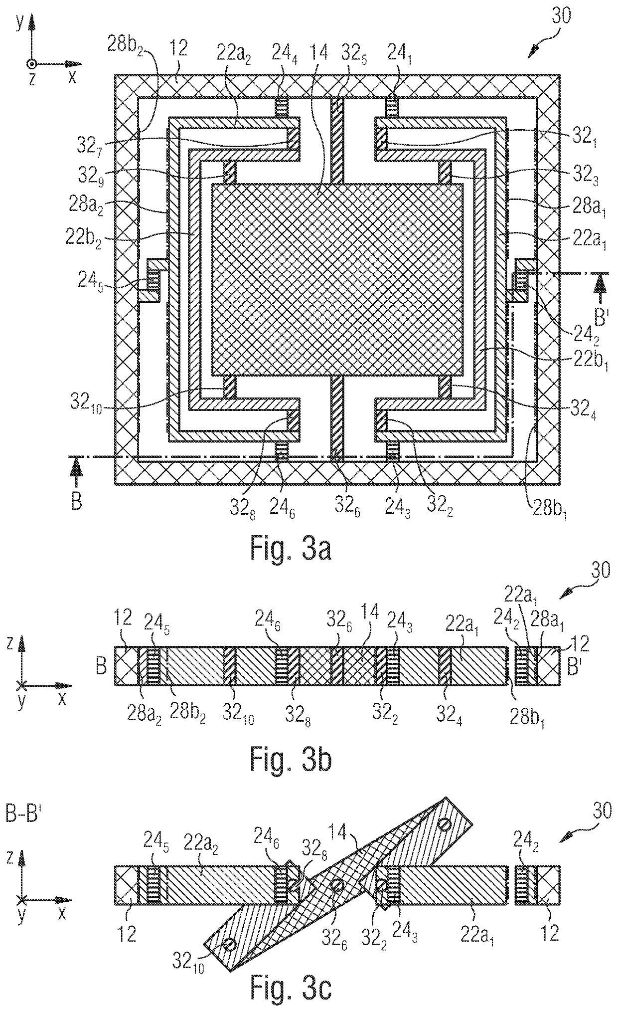
A micromechanical apparatus includes a substrate, a movable element disposed in a reference plane in an undeflected state, a transmission structure having a first transmission side coupled to the substrate, and a second transmission side coupled to the movable element, and an actuator configured to provide a force along a force direction parallel to the reference plane and apply the same to the first transmission side. The transmission structure is configured to transfer the force along the force direction to a movement of the movable element out of the reference plane.

Description

CROSS-REFERENCE TO RELATED APPLICATIONS[0001]This application is a continuation of copending International Application No. PCT / EP2020 / 054863, filed Feb. 25, 2020, which is incorporated herein by reference in its entirety, and additionally claims priority from German Application No. 102019202656.7, filed Feb. 27, 2019, and from German Application No. 102019202658.3, filed Feb. 27, 2019, both of which are also incorporated herein by reference in their entirety.BACKGROUND OF THE INVENTION[0002]The present invention relates to a micromechanical structure, and more particularly to a micromechanical structure having a movable element deflectable out of a reference plane. The present invention also relates to a micromechanical system, to an apparatus comprising a micromechanical structure or a micromechanical system, and to a method of providing a micromechanical structure. The present invention further relates to linearizable resonant devices.[0003]To move micro-electro-mechanical systems...

Claims


Application Information

Patent Timeline
IPC IPC(8): B81B3/00G02B26/08
CPCB81B3/0051G02B26/0841B81B2203/0154B81B2203/04B81B2203/051B81B2201/037B81B2201/035B81B2201/042B81B2203/058B81B2201/033G02B26/0833G02B26/0808B81B2203/053
Inventor DRABE, CHRISTIANDREYHAUPT, ANDRÉ
Owner FRAUNHOFER GESELLSCHAFT ZUR FOERDERUNG DER ANGEWANDTEN FORSCHUNG EV
Learn More