
Method for representing an environment of a mobile platform

a mobile platform and environment technology, applied in the direction of vehicle position/course/altitude control, using reradiation, instruments, etc., can solve the problems of computation-time and memory footprint etc., to achieve constant computational and memory complexity

Pending Publication Date: 2021-12-09
ROBERT BOSCH GMBH
View PDF0 Cites 1 Cited by
  • Summary
  • Abstract
  • Description
  • Claims
  • Application Information

AI Technical Summary

Benefits of technology

The present invention provides a method to predict the environment of a moving platform at a given time using data from multiple sensors. This method is modular, allowing for easy interpretation by experts. Additionally, the resulting environment representation can be used for identifying the root cause of faults in the system, using a deep neural net. The map can also be used to directly or indirectly inform passengers of the current situation. This method may increase trust in the operation of at least partially autonomous systems and make them work more correctly.

Problems solved by technology

Sensor-data originated by sensor types which directly provide physical data do not provide semantic information.
To represent the environment using a unified moving spatial reference system for all the different sensor-data of a plurality of sensors, results in a constant computational and memory complexity and in a computation-time and memory footprint of the representation of the environment, which is independent from the density or respectively number of nearby objects in the scene of the environment.
Hence, a grid-based representation of sensor-data has constant computational and memory complexity.
If such a critical situation would be detected using the environment representation as described as input to a decision system it may lead to an emergency brake or an early slow down of the speed controlled by the supporting emergency brake system.

Method used


Image

  • Method for representing an environment of a mobile platform
  • Method for representing an environment of a mobile platform
  • Method for representing an environment of a mobile platform

Examples


Embodiment Construction

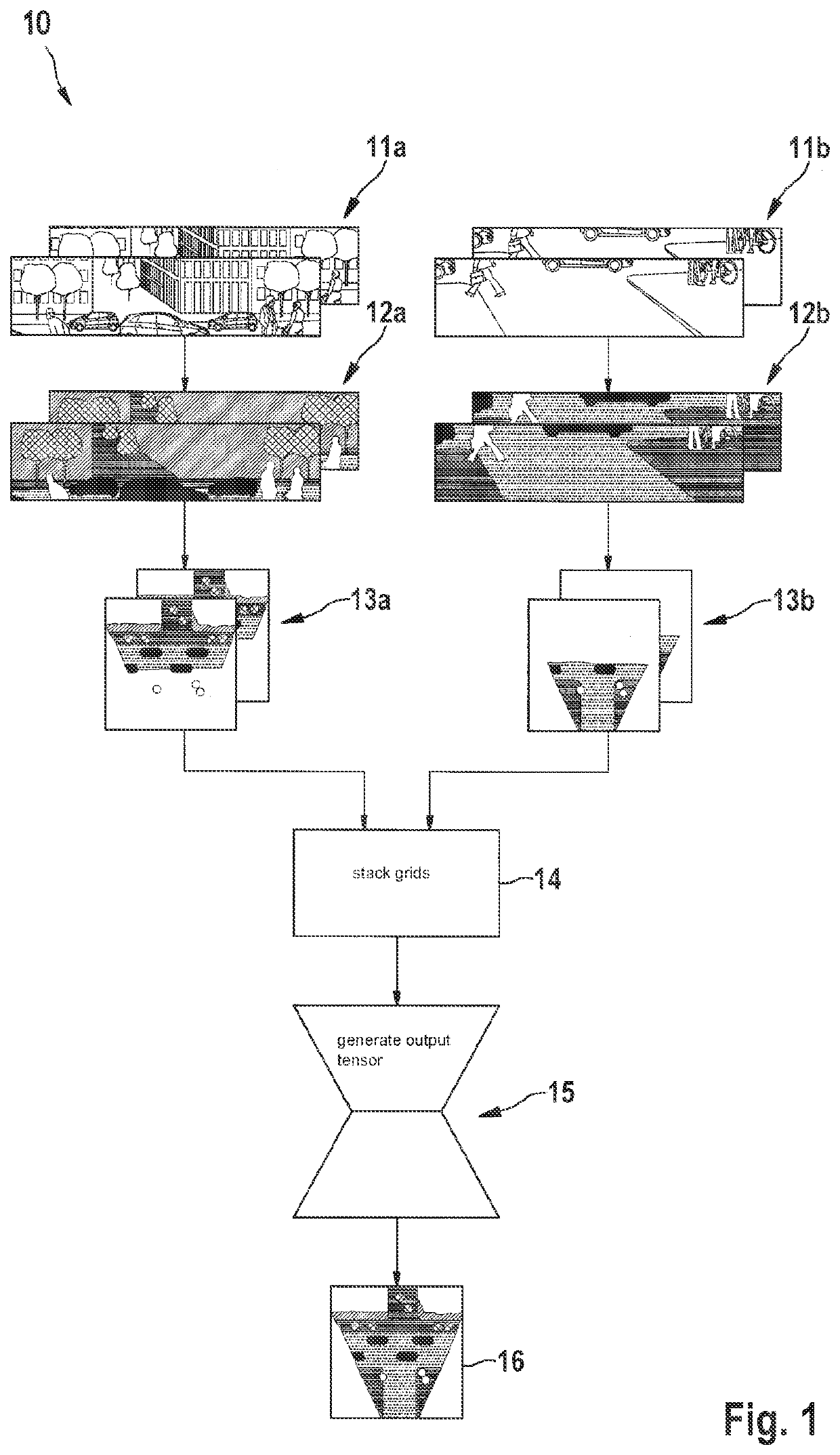
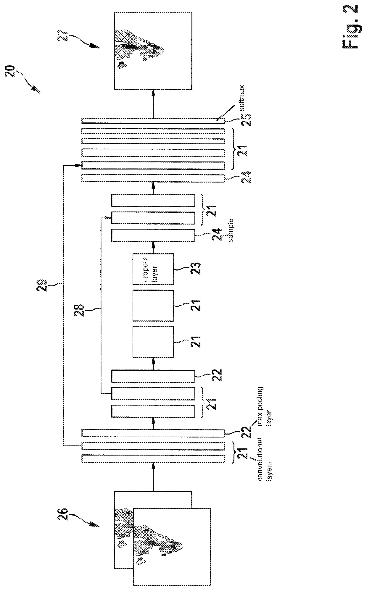
[0081]A schematic overview on an embodiment of the method for representing an environment of a first mobile platform is shown in FIG. 1. The features of the environment are captured by discrete time sequences of sensor data of two sensors, which are represented here as image sequences 11a, 11b of two digital cameras from past times. The respective time markers of the images are recorded when they were taken and are captured together with the images. The at least two sequences of images may be taken at a different rate and at different times.

[0082]The two digital cameras characterize with their sequences of digital images the environment of a mobile platform and may be mounted at the platform or outside of the platform or one at the platform and the other sensor at a defined site outside of the platform. Alternatively at least one sensor is mounted at another mobile platform. The part of the environment, which is characterizes by the sensors, may be different. That means that, e.g., ...


PUM


Abstract

A method and system for representing an environment of a first mobile platform. The method includes: capturing features of the environment by discrete time sequences of sensor-data from at least two sensors and respective time markers; determining distances of the first mobile platform to the features of the environment; estimating semantic information of the features of the environment; transforming the semantic information of the features of the environment into a moving spatial reference system, wherein a position of the first mobile platform is at a constant site, using the respective determined distances and respective time markers; creating an input tensor using sequences of the transformed semantic information of the features of the environment, corresponding to the sequences of the sensor data of the at least two sensors; generating an output tensor that represents the environment using a deep neural network at a requested point in time and the input tensor.

Description

FIELD[0001]The present invention relates to a method for representing an environment of a mobile platform as well as a systems configured to execute the method, wherein the environment is characterized by sequences of data of a plurality of sensors.BACKGROUND INFORMATION[0002]Deep learning methods have been investigated for controlling at least partially autonomous systems, such as self-driving vehicles, or robots as examples for mobile platforms. An essential part of such at least partially autonomous systems is their capability to perceive complex situations in respect to their environment.[0003]A requirement for such an at least partially autonomous system to operate safely and effectively is to interpret its surrounding environment, and estimate the state of this environment over time for, e.g., decision-making processes, such as motion planning and control.[0004]In order to enable intelligent decision making, a common interface between a plurality of different sensors for perce...

Claims


Application Information

Patent Timeline
IPC IPC(8): G05D1/02G06K9/00G06K9/62G06N3/04G01S13/931G01S13/89G06V10/764
CPCG05D1/0246G06K9/00791G06K9/629G05D1/0257G01S2013/9324G06N3/04G01S13/931G01S13/89G01S2013/9323G05D1/0255G06N3/082G01S13/867G01S13/865G01S17/86G01S17/931G06V20/20G06V20/56G06V10/82G06V10/764G06N3/048G06N3/045G06F18/253G05D1/249G05D1/247
Inventor HOYER, LUKASFISCHER, VOLKER
Owner ROBERT BOSCH GMBH
Learn More