Acoustic detection of small unmanned aircraft systems

Pending Publication Date: 2021-12-09
APPLIED RES ASSOCS INC
View PDF15 Cites 0 Cited by
  • Summary
  • Abstract
  • Description
  • Claims
  • Application Information

AI Technical Summary

Benefits of technology

[0008]A second embodiment of the invention is directed to a system for non-line-of-sight passive detection and integrated early warning of an unmanned aerial system, the system comprising a plurality of geo-located acoustic sensors in depth within an intra-connected array according to at least one of a terrain, terrain features, or man-made objects or structures, at least one acoustic sensor of the plurality of acoustic sensors receiving an acoustic signal, and a processor. The system also comprises acoustic sensors with integrated electro-optical imaging components operated in an orthogonal manner for further enhancing confidence in detection of UAS. The system further comprises one or more non-transitory computer-readable media storing computer-executable instructions that, when executed by the processor, perform a method of classifying a source of the acoustic signal. The method comprises the step of comparing a signal indicative of at least a portion of the acoustic signal with known characteristic signals to classify the source of the acoustic signal, wherein the known characteristic signals include information indicative of unmanned aerial systems.
[0009]A third embodiment of the invention is directed to a system for non-l

Problems solved by technology

However, small UAS still may elude these line-of-sight detection methods as they can fly nap-of-the-earth, leverage terrain features for cover and concealment, and/or move unpredictably within high clutter, low-altitude areas.
Furthermore, UAS may be extremely difficult to detect using radar and/or electro-optical systems.
Therefore, the current methods do not allow for detection in complex urban settings, behind hills, and in valleys where attacking UAS may

Method used


Image

  • Acoustic detection of small unmanned aircraft systems
  • Acoustic detection of small unmanned aircraft systems
  • Acoustic detection of small unmanned aircraft systems

Examples


Embodiment Construction

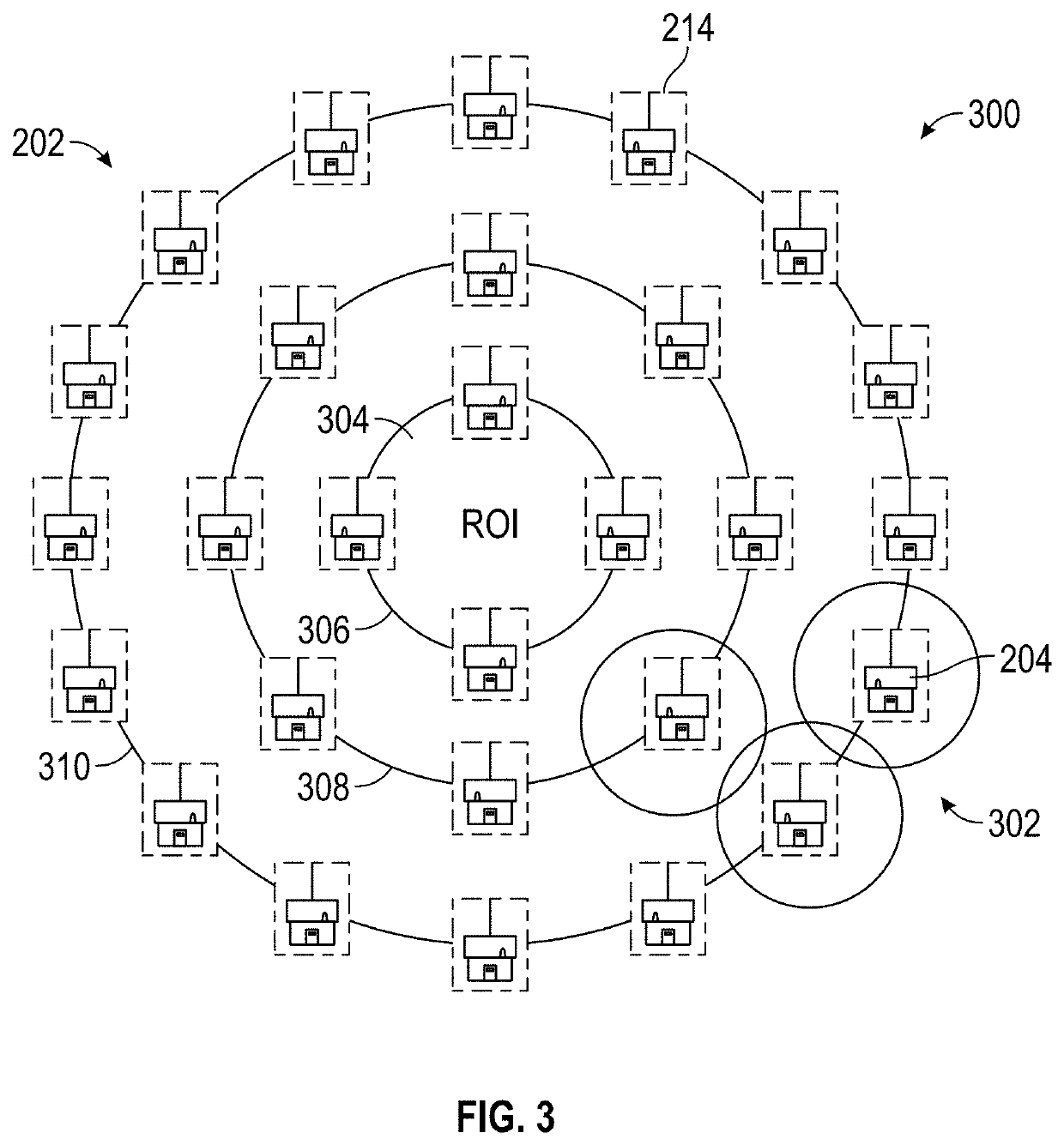
[0020]Embodiments of the invention solve the above-described problems and provide a distinct advance in the field by providing a method and system for passively detecting UAS. In some embodiments, acoustic sensors may be arranged in arrays. The acoustic sensors may detect vibrations in the air and ground as derived from UAS propeller rotations. The signal measured by the acoustic sensors may be compared to a database of known sensors to determine the source of the signal and if the source of the signal is friendly or a possible threat. In some embodiments, acoustic sensors may have integrated electro-optical imaging components operated in an orthogonal manner for further enhancing confidence in detection of UAS. In some embodiments, detection of the UAS may trigger additional sensors and systems and methods for countering the threat.

[0021]Though UAS are described in embodiments herein, it should be recognized that any vehicle may be detected and recognized. For example, the vehicle ...


PUM


Abstract

Systems and methods of non-line-of-sight passive detection and integrated early warning of an unmanned aerial system by a plurality of acoustic sensors are described. In some embodiments, the plurality of acoustic sensors is positioned within an intra-netted array in depth according to at least one of a terrain, terrain features, or man-made objects or structures. The acoustic sensors are capable of detecting and tracking unmanned aerial systems in non-line-of-sight environments. In some embodiments, the acoustic sensors may be in communication with internal electro-optical components or other external sensors, with orthogonal signal data then transmitted to remote observation stations for correlation, threat determination and if required, mitigation. The unmanned aerial systems may be classified by type and a threat level associated with the unmanned aerial system may be determined.

Description

RELATED APPLICATIONS[0001]This application claims priority benefit of U.S. Provisional Application No. 63 / 036,575, filed Jun. 9, 2020, and entitled “ACOUSTIC DETECTION OF SMALL UNMANNED AIRCRAFT SYSTEMS,” which is herein incorporated by reference in its entirety.BACKGROUND1. Field[0002]Embodiments of the invention relate to systems and methods for detecting small unmanned aerial systems. More specifically, embodiments of the invention relate to the employment of intra-netted acoustic detection of small unmanned aerial systems in 360-degrees of terrain-independent coverage with multiple radii in depth.2. Related Art[0003]Typical systems and methods of detecting Unmanned Aerial Systems (UAS) employ radar, visible optics, thermal optics and / or radio frequency detection. However, small UAS still may elude these line-of-sight detection methods as they can fly nap-of-the-earth, leverage terrain features for cover and concealment, and / or move unpredictably within high clutter, low-altitude...

Claims


Application Information

Patent Timeline
IPC IPC(8): G08B13/196G08G5/00G08B13/16
CPCG08B13/19676G08B13/1672G08G5/0073G08G5/0026G08G5/0052G08G5/0069G08G5/0082G08G5/0091H04R2201/401H04R5/027H04R3/005H04R2430/23
Inventor SERINO, ROBERT M.MCKENNA, MARK J.HAAS, JOHN
Owner APPLIED RES ASSOCS INC
Why Eureka
Try Eureka