
User station for a serial bus system and method for communication in a serial bus system

Pending Publication Date: 2021-12-16
ROBERT BOSCH GMBH
View PDF3 Cites 0 Cited by
  • Summary
  • Abstract
  • Description
  • Claims
  • Application Information

AI Technical Summary

Benefits of technology

The present invention provides a user station for a serial bus system and a method for communication that can solve problems of high data rate and increased useful data per frame with great flexibility and error tolerance. The communication protocol used by the user station is simpler and more functionally reliable, and can easily expand for future needs without changing the frame format. The design of the user station allows for communication of various types of information without changing the frame format. This ensures transmitting and receiving of frames with great flexibility and lower error rate even upon increase of the data rate. The user station can maintain an arbitration known from CAN and significantly increase the transfer rate in relation to CAN or CAN FD.

Problems solved by technology

However, such an association does not scale well and is not flexible enough.

Method used


Image

  • User station for a serial bus system and method for communication in a serial bus system
  • User station for a serial bus system and method for communication in a serial bus system
  • User station for a serial bus system and method for communication in a serial bus system

Examples


Embodiment Construction

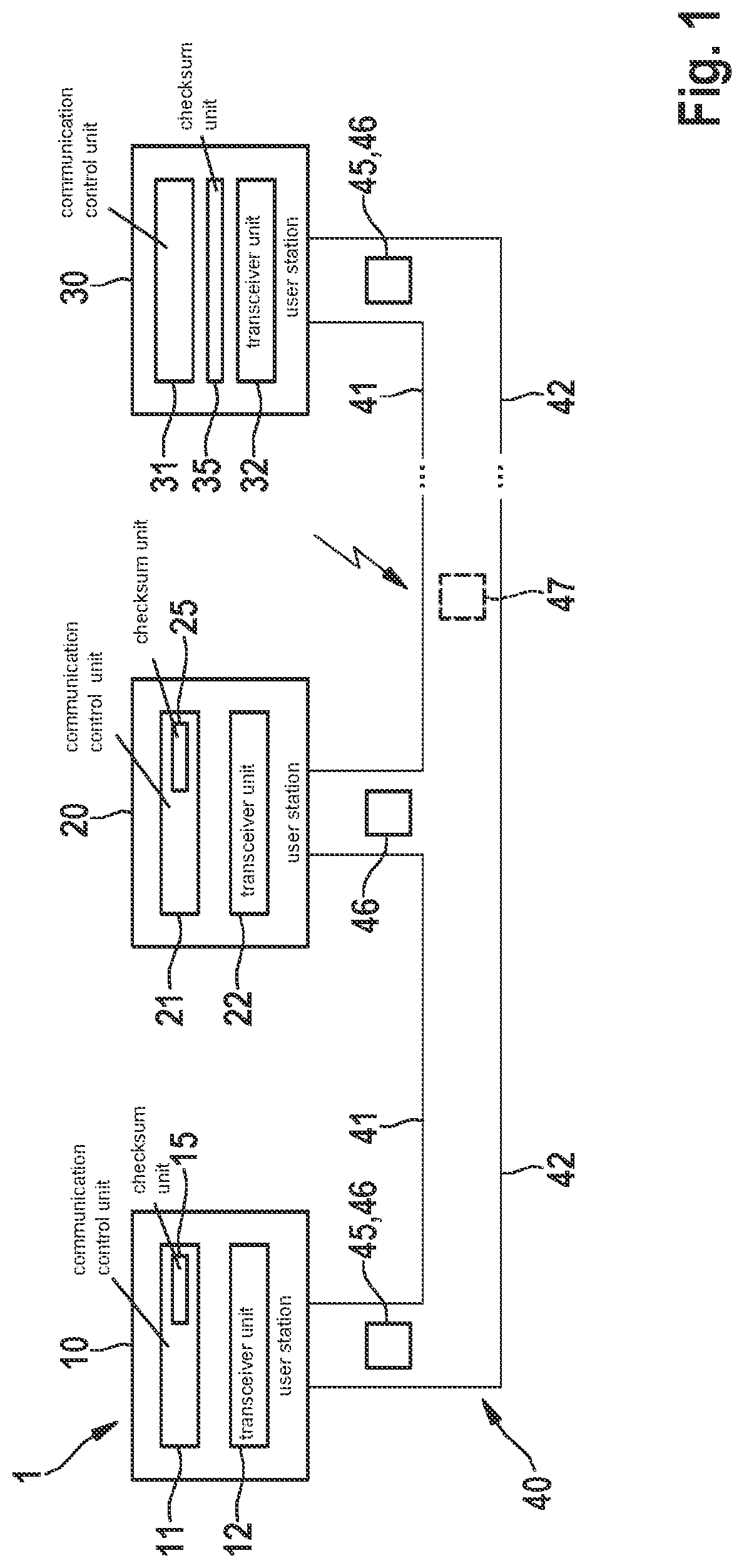
[0040]FIG. 1 shows as an example a bus system 1, which is designed in particular as the foundation for a CAN bus system, a CAN FD bus system, a CAN FX bus system, and / or modifications thereof, as described hereinafter. Bus system 1 may be used in a vehicle, in particular a motor vehicle, an aircraft, etc., or in a hospital, etc.

[0041]In FIG. 1, bus system 1 includes a plurality of user stations 10, 20, 30, which are each connected to a bus 40 having a first bus wire 41 and a second bus wire 42. Bus wires 41, 42 may also be called CAN H and CAN L or CAN-FX H and CAN-FX L and are used for electrical signal transmission after coupling in the dominant level or generating recessive levels for a signal in the transmit state. Messages 45, 46 are serially transmittable in the form of signals between individual user stations 10, 20, 30 via bus 40. If an error occurs during the communication on bus 40, as shown by the serrated black block arrow in FIG. 1, an error frame 47 (error flag) may op...


PUM


Abstract

A user station for a serial bus system and a method for communication in a serial bus system. The user station includes a communication control unit, and a transceiver unit for transmitting a transmit signal for a message which is exchanged between user stations of the bus system. The bit time of a signal transmitted in the first communication phase on the bus differs from a bit time of a signal transmitted in the second communication phase. The communication control unit generates the transmit signal according to a frame, in which in addition to a field which indicates the priority of the message, a field for a data type is provided, and the communication control unit being designed to write a value in the field for the data type which indicates which type of information is located in a data field of the frame.

Description

FIELD[0001]The present invention relates to a user station for a serial bus system and a method for communication in a serial bus system, using which in addition to data transport alone, other functions are also assisted, such as safety (functional safety), security (data security), and QoS (quality of service, for example guarantee of a maximum latency for a frame, time synchronization of the user stations (nodes) in the bus system).BACKGROUND INFORMATION[0002]For communication between sensors and control units, for example in vehicles, for reasons of cost, instead of a point-to-point connection, a bus system is presently being used more and more frequently, in which data are transferred as messages in the standard ISO 11898-1:2015 as the CAN protocol specification using CAN FD. The messages are transferred between the user stations of the bus system, such as sensor, control unit, encoder, etc. CAN FD is usually presently used in the vehicle in the introduction phase in the first s...

Claims


Application Information

Patent Timeline
IPC IPC(8): H04L12/40
CPCH04L12/4013H04L12/40163H04L12/40032H04L12/40013H04L12/40169H04L2012/40215H04L12/40143
Inventor MUTTER, ARTHURHARTWICH, FLORIAN
Owner ROBERT BOSCH GMBH
Features
  • Generate Ideas
  • Intellectual Property
  • Life Sciences
  • Materials
  • Tech Scout
  • Unparalleled Data Quality
  • Higher Quality Content
  • 60% Fewer Hallucinations
Learn More