Bone age assessment method for bone image

a bone image and bone age technology, applied in image enhancement, tomography, instruments, etc., can solve the problems of long reading time, deviation, and different focus areas

Pending Publication Date: 2021-12-23
VUNO INC
View PDF0 Cites 1 Cited by
  • Summary
  • Abstract
  • Description
  • Claims
  • Application Information

AI Technical Summary

Benefits of technology

[0016]Alternatively, the one or more partial bone images may be generated based on one or more major points and a size of a partial bone image corresponding to the one or more major points, and the one or more major points may be determined based on a probability that each of one or more points comprised in the whole bone image corresponds to a major point, and the size of a partial bone image may be determined based on a type of the one or more major points.
[0017]In order to solve the foregoing technical problems in the related art, there is disclosed a computing device estimating bone age from a bone image. The computing device may comprise: a memory comprising computer executable components; and a processor that executes the following computer executable components stored in the memory, in which the processor is configured to: estimate a RUS score for each of one or more partial bone images using a partial bone RUS score estimation model comprising one or more layers, in which the one or more partial bone images are generated from a whole bone image; and estimate bone age corresponding to the whole bone image using one or more RUS scores estimated for each of the one or more partial bone images, and the partial bone RUS score estimation model is trained by using a labeled partial bone image as training data, and is trained by adjusting feature values calculated from the one or more layers.
[0018]In order to solve the foregoing technical problems in the related art, there is disclosed a method of estimating bone age from a bone image by computing device. The method comprises: estimating a RUS score for

Problems solved by technology

The GP measurement method enables a reader to quickly check the test result, but there is a problem that a focused area may be different depending on a reader and some deviations occur.
Unlike the GP measurement method, the TW3 measurement method g

Method used


Image

  • Bone age assessment method for bone image
  • Bone age assessment method for bone image
  • Bone age assessment method for bone image

Examples


Embodiment Construction

[0030]Various embodiments are described with reference to the drawings. In the present specification, various descriptions are presented for understanding the present disclosure. However, it is obvious that the embodiments may be carried out even without a particular description.

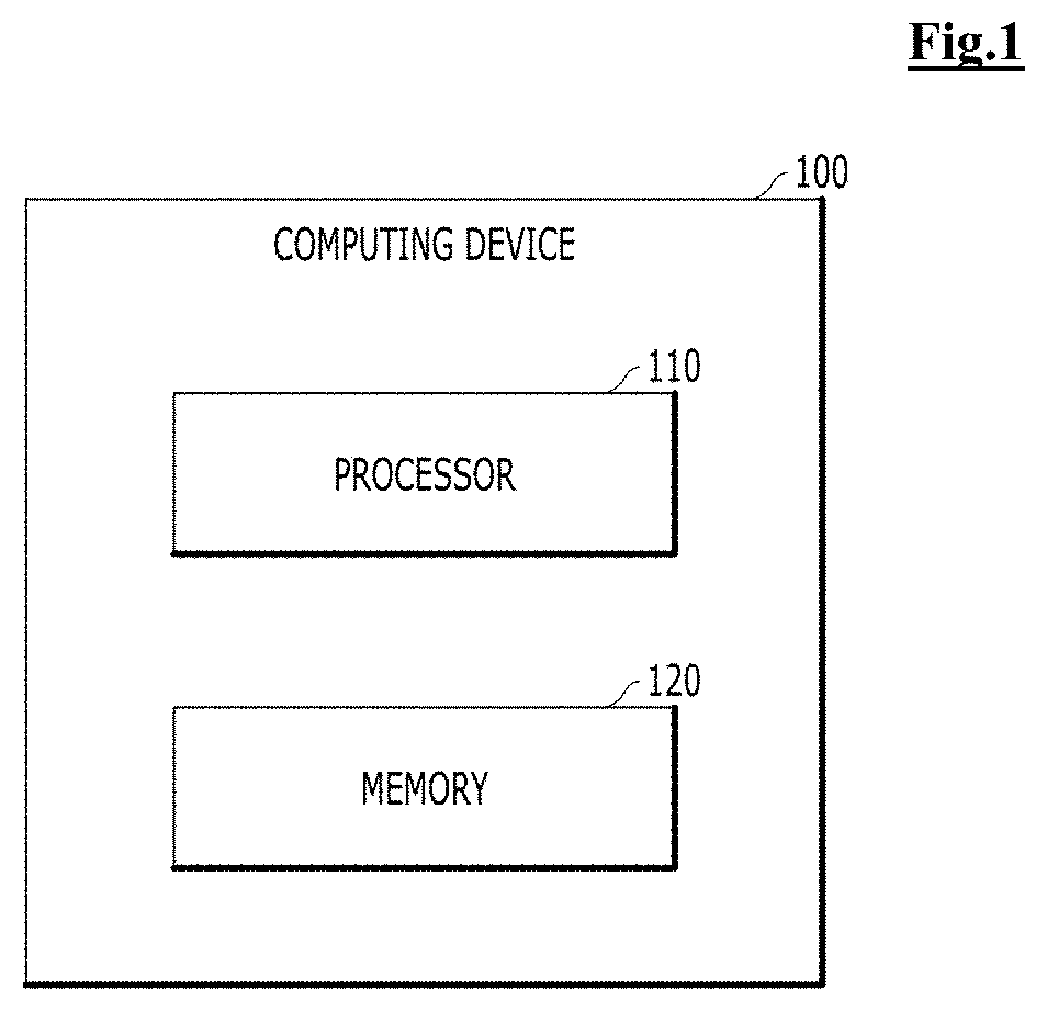
[0031]Terms, “component,”“module,”“system,” and the like used in the present specification indicate a computer-related entity, hardware, firmware, software, a combination of software and hardware, or execution of software. For example, a component may be a procedure executed in a processor, a processor, an object, an execution thread, a program, and / or a computer, but is not limited thereto. For example, both an application executed in a computing device and a computing device may be components. One or more components may reside within a processor and / or an execution thread. One component may be localized within one computer. One component may be distributed between two or more computers. Further, the compon...


PUM


Abstract

According to an embodiment of the present disclosure, a computer program stored in a computer readable storage medium is disclosed. The computer program includes instructions for causing one or more processors to estimate bone age from a bone image, and the instructions include: estimating a RUS score for each of one or more partial bone images using a partial bone RUS score estimation model comprising one or more layers, and wherein the one or more partial bone images are generated from a whole bone image; and estimating bone age corresponding to the whole bone image using one or more RUS scores estimated for each of the one or more partial bone images, in which the partial bone RUS score estimation model is trained by using a labeled partial bone image as training data, and is trained by adjusting feature values calculated from the one or more layers.

Description

CROSS-REFERENCE TO RELATED APPLICATIONS[0001]This application claims priority to and the benefit of Korean Patent Application No. 10-2020-0076520 filed in the Korean Intellectual Property Office on Jun. 23, 2020, and Korean Patent Application No. 10-2020-0092344 filed in the Korean Intellectual Property Office on Jul. 24, 2020 the entire contents of which are incorporated herein by reference.BACKGROUNDTechnical Field[0002]The present disclosure relates to a method of measuring bone age by using a machine learning module, and particularly, to a machine learning module which measures bone age from a bone image.Description of the Related Art[0003]In order to read bone age from a bone image in the related art, the Grulich-Pyle (GP) method and the Tanner-Whitehouse 3 (TW3) method were used.[0004]The GP measurement method measures bone age by comparing and analyzing the hand bone photos of a target child by referring to the standard drawing of hand bone photos standardized by bone age at ...

Claims


Application Information

Patent Timeline
IPC IPC(8): G06T7/00G16H50/30G16H50/20G06N3/04A61B5/00
CPCG06T7/0012G16H50/30G16H50/20G06N3/0472G06T2207/20182G06T2207/30008G06T2207/20081G06T2207/20084A61B5/4504A61B2503/06A61B5/7267A61B5/055A61B5/7246A61B5/004A61B5/1075A61B6/5217A61B6/505A61B6/032A61B8/0875A61B8/5223G16H30/40G06T2207/10116G06N3/084G06N3/045G06N3/047
Inventor BAE, BYEONGUKJUNG, KYUHWAN
Owner VUNO INC
Why Eureka
Try Eureka