
Printed circuit board connector

a technology of printed circuit boards and connectors, applied in the direction of coupling devices, coupling contact members, coupling devices, etc., can solve the problems of complex and cost-intensive design, and achieve the effect of good results, cost-efficient and reliabl

Active Publication Date: 2021-12-23
HUBERSUHNER AG
View PDF19 Cites 1 Cited by
  • Summary
  • Abstract
  • Description
  • Claims
  • Application Information

AI Technical Summary

Benefits of technology

The invention is a special connector design that combines the inner and outer conductors in a coaxial cable in a special way. This design has several advantages, including a simpler design, lower cost, and the possibility to avoid moving and vibrating galvanic contacts. The design also allows for high-order low pass filtering, which can be useful in certain applications. The connector can be designed to fit specific frequencies and can be attached to circuit boards or cables. The design uses a meander shaped grid section and a spiral spring center contact to achieve the high-order low pass filtering. The inner conductor can have contact means to connect to the circuit board, and the outer conductor can have a polygonal cross-section to further enhance the filtering function.

Problems solved by technology

The mechanical spring characteristic, which is used for axial misalignment compensation, is separate from the electrical path of the connector, mainly because of undesirable electrical effects.
This results in a complex and cost intensive design.

Method used


Image

  • Printed circuit board connector
  • Printed circuit board connector
  • Printed circuit board connector

Examples


Embodiment Construction

[0045]Reference will now be made in detail to certain embodiments, examples of which are illustrated in the accompanying drawings, in which some, but not all features are shown. Indeed, embodiments disclosed herein may be embodied in many different forms and should not be construed as limited to the embodiments set forth herein; rather, these embodiments are provided so that this disclosure will satisfy applicable legal requirements. Whenever possible, like reference numbers will be used to refer to like components or parts.

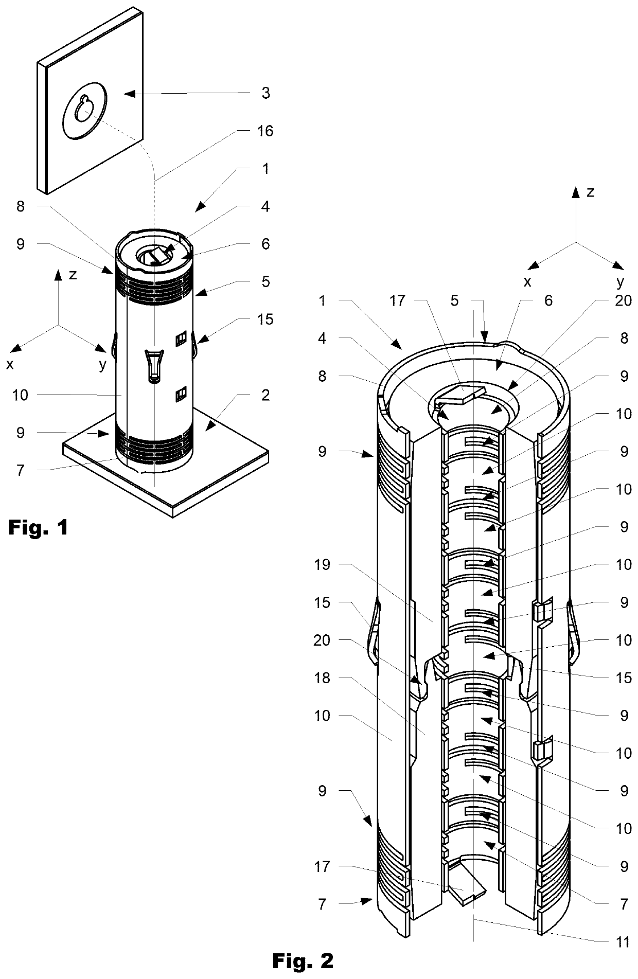
[0046]FIG. 1 illustrates a first variation of a coaxial connecting member 1 according to the invention, arranged between a first and a second circuit board 2, 3. In the final position, the first and the second circuit board are spaced apart from each other by a certain distance. In the shown drawing, the second circuit board 3 is shown in a detached manner. The direction of assembly is schematically indicated by a dotted line 16.

[0047]FIG. 2 illustrates the coaxi...


PUM


Abstract

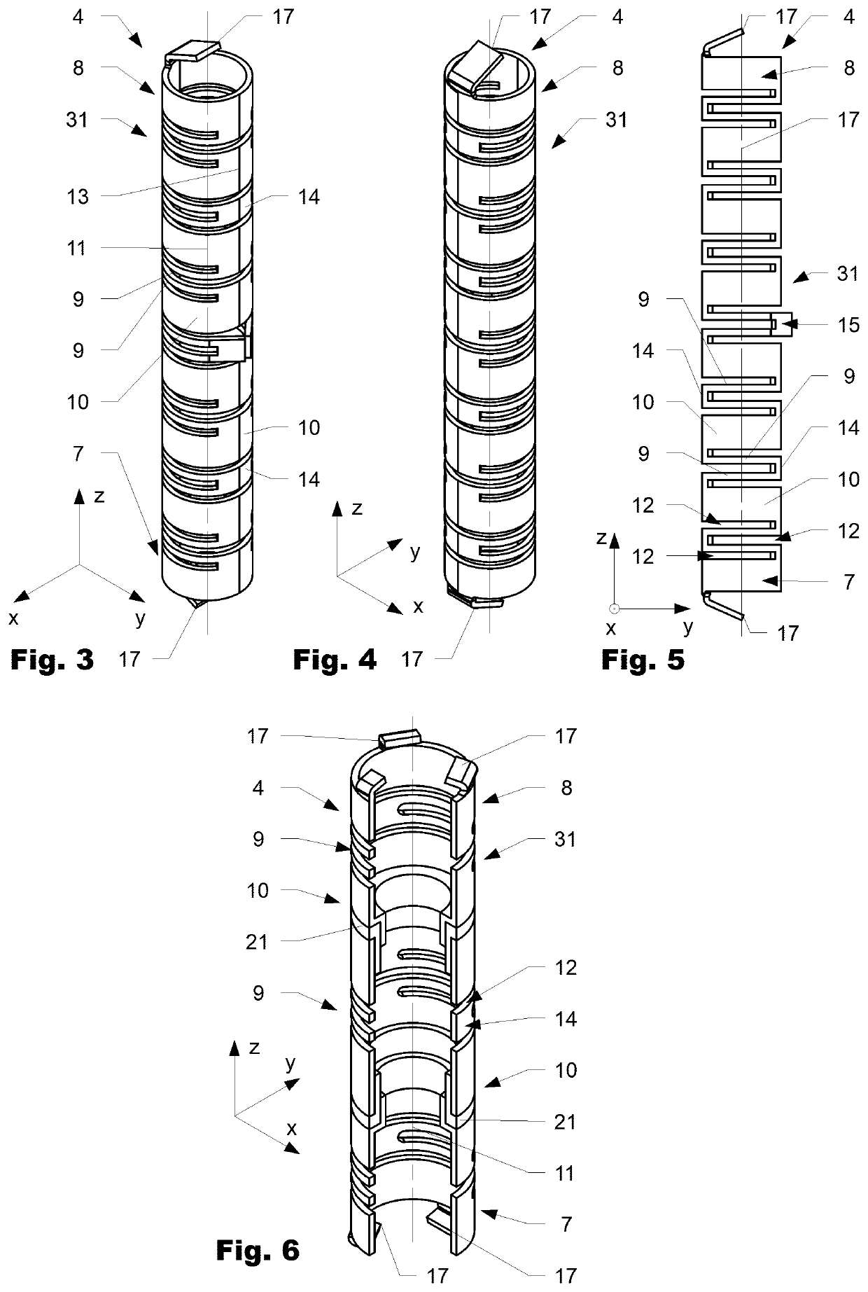
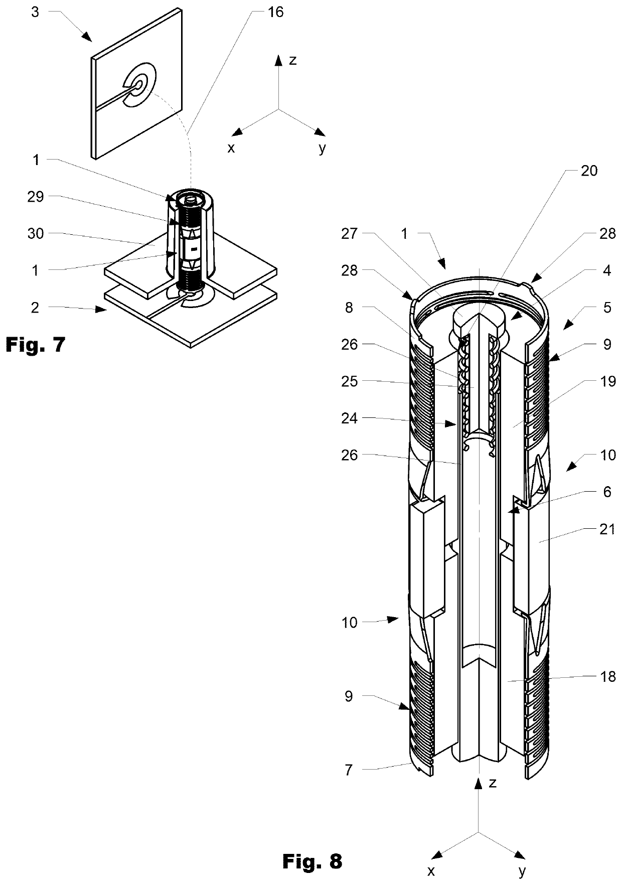
A coaxial connecting member (1) for transmitting radio-frequency signals between a first and a second circuit board (2, 3) includes an inner conductor (4), an outer conductor (5) and an insulating member (6) arranged between the inner conductor (4) and the outer conductor (5). The inner conductor (4) and / or the outer conductor (5) comprise a first and a second end section (7, 8) to interconnect the inner conductor (4) to the first and the second circuit board (2, 3). The first and the second end section (7, 8) are interconnected to each other by at least one elastically deformable transversal section (9) to compensate axial and / or lateral misalignment of the first and the second circuit board (2, 3) with respect to each other.

Description

CROSS REFERENCE TO RELATED APPLICATION[0001]This application is a National Phase filing in the United States, under 35 USC § 371, of PCT International Patent Application PCT / EP2019 / 080975, filed on 12 Nov. 2019 which claims the priority of Swiss Patent Application CH 01389 / 18, filed 12 Nov. 2018.[0002]These applications are hereby incorporated by reference herein in their entirety and is made a part hereof, including but not limited to those portions which specifically appear hereinafter.BACKGROUND OF THE INVENTIONField of the Invention[0003]The present invention relates to a printed circuit board connector (PCB Connector).Discussion of Related Art[0004]EP 2780985B1, published in December 2016 and U.S. Pat. No. 9,300,063B2 published in March 2016, both in the name of Rosenberger Hochfrequenztechnik GmbH, are directed to a connector for the electrically conductive connection of two components. The coaxial connector is configured to connect two printed circuit boards for transmitting ...

Claims


Application Information

Patent Timeline
Patent Type & Authority Applications(United States)
IPC IPC(8): H01R12/91H01R24/42H01R12/71H01R12/70H01R13/24
CPCH01R12/91H01R24/42H01R2103/00H01R12/7082H01R13/2428H01R12/712H01R12/73H01R24/50H01P1/202
Inventor WAGNER, MARTINMANSER, FRANZHILDEBRAND, RUDOLFSTUFFER, MICHAEL
Owner HUBERSUHNER AG
Learn More