
Motorcycle light for realizing at least one light function

a technology of motorcycle lights and functions, applied in the field of motorcycle lamps, can solve the problems of difficult cleaning of the light-emission surface, difficulty in achieving values, uneven light-emission surface of the front optics, etc., and achieve the effect of high precision, high precision and high precision

Active Publication Date: 2021-12-30
MOTOGADGET
View PDF0 Cites 0 Cited by
  • Summary
  • Abstract
  • Description
  • Claims
  • Application Information

AI Technical Summary

Benefits of technology

The patent text describes a motorbike signal lamp with a curved surface that scatters the light beams in both the horizontal and vertical directions. This results in better visibility and a smaller size of the lamp. Additionally, if there are multiple light sources, they should all be directed towards the same direction to ensure proper visibility.

Problems solved by technology

With the known lamp, these values can only be achieved with the help of the additional optical elements on the light-emission surface of the front optics.
The disadvantage of the optical elements is that the light-emission surface of the front optics is not smooth, i.e., dirt, insects or the like can easily stick.
In addition, the protruding optical elements render the light-emission surface is difficult to clean.
This disadvantage is exacerbated by the fact that edges form at the transition between the light-emission surface of the front optics and the optical elements, in which edges dirt and insects can adhere in a particularly persistent manner.

Method used


Image

  • Motorcycle light for realizing at least one light function
  • Motorcycle light for realizing at least one light function
  • Motorcycle light for realizing at least one light function

Examples


Embodiment Construction

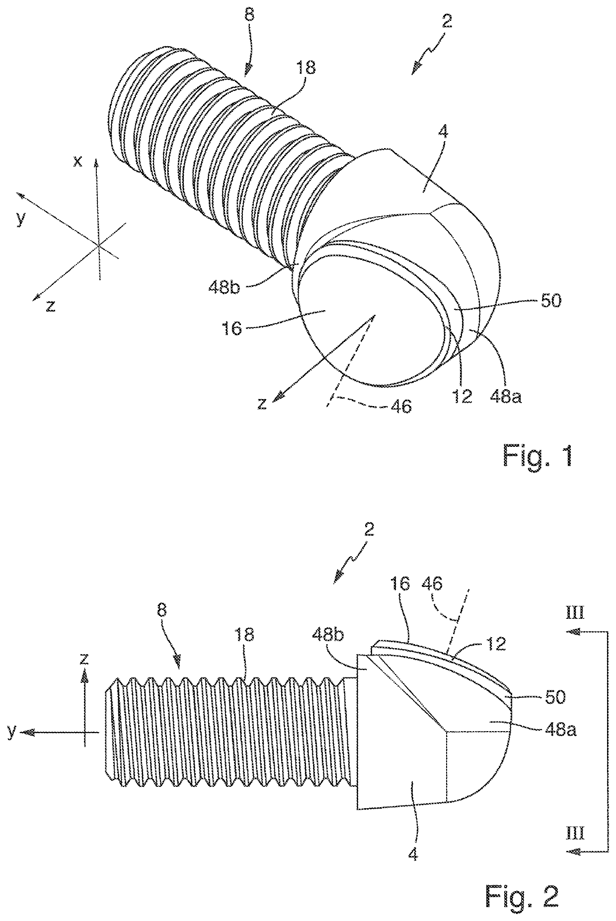
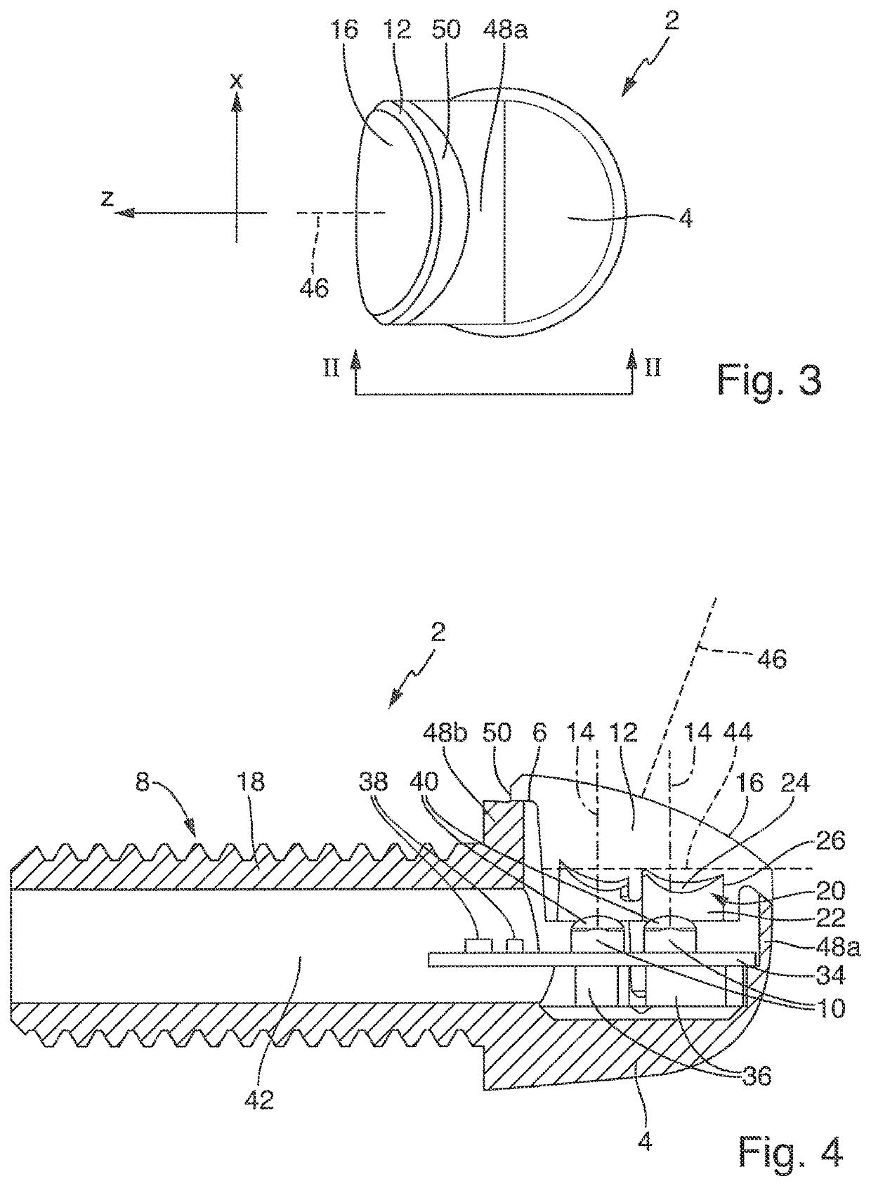
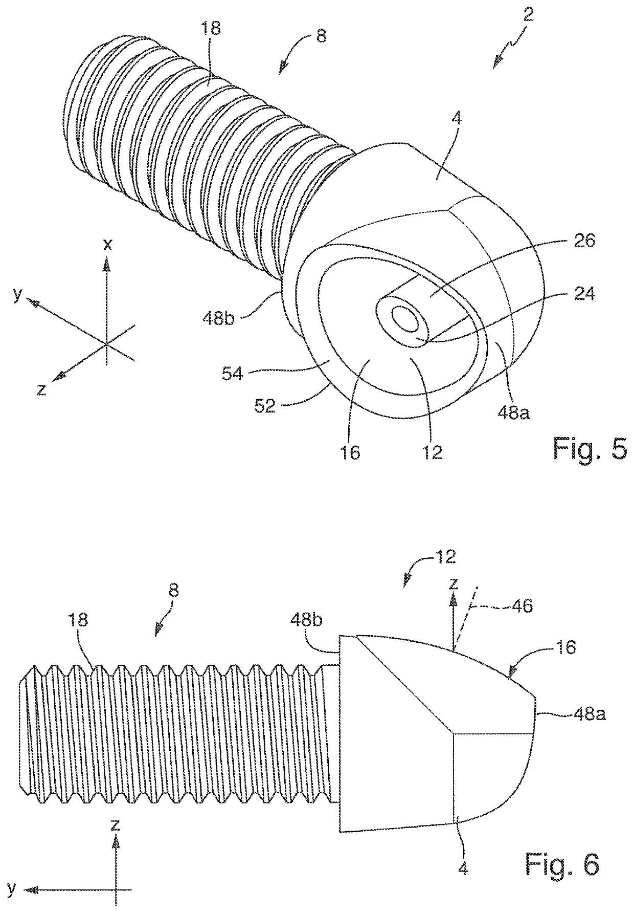
[0056]The motorcycle lamp according to the invention of FIGS. 1-4 is designated in its entirety by the reference numeral 2. It is used to implement at least one lamp function, e.g. flashing light, marker light, bend lighting, taillight and / or brake light. The motorcycle lamp 2 comprises

[0057]a housing 4 having a light-emission aperture 6 (cf. FIG. 4),

[0058]a bracket 8 mounted on the housing 4 for securing the motorcycle lamp 2 to a motorcycle,

[0059]at least one light source 10 disposed in the housing 4 (cf. FIG. 4), and

[0060]a front optics 12 made of a solid transparent material, such as glass or plastic, disposed between the at least one light source 10 and the light-emission aperture 6. The at least one light source 10 comprises an LED or any other semiconductor light source (e.g. OLED, laser LED) and is disposed and aligned in the housing 4 such that it emits light in a main radiation direction 14 (cf. FIG. 4) extending through the light-emission aperture 6. The front optics 12 c...


PUM


Abstract

The invention relates to a motorcycle lamp (2) for implementing at least one lamp function. The motorcycle lamp (2) comprisesa housing (4) having a light-emission aperture (6),a bracket (8) mounted on the housing (4) for securing the motorcycle lamp (2) to a motorcycle,at least one light source (10) disposed in the housing (4) anda front optics (12) made of a solid transparent material disposed between the at least one light source (10) and the light-emission aperture (6),wherein the at least one light source (10) comprises an LED and is disposed and oriented in the housing (4) such that it emits light in a main radiation direction (14) extending through the light-emission aperture (6), andwherein the front optics (12) closes the light-emission aperture (6) and deflects and shapes the light emitted by the at least one light source (10) to generate a light distribution corresponding to a lamp function implemented by the motorcycle lamp (2). In order for the lamp (2) to improve the lateral perceptibility without the use of additional optical elements in the optical path, it is proposed that a light-emission surface (16) of the front optics (12) has a first convex curvature when viewed in a horizontal plane (yz) and a second convex curvature when viewed in a vertical plane (xz), the latter being smaller than the first convex curvature in the horizontal plane (yz) or flat.

Description

BACKGROUND OF THE INVENTION1. Field of Invention[0001]This invention relates to a motorcycle lamp for implementing at least one lamp function. The motorcycle lamp includes[0002]a housing having a light-emission aperture,[0003]a bracket mounted on the housing for securing the motorcycle lamp on a motorcycle,[0004]at least one light source disposed in the housing and[0005]a front optics made of a solid transparent material disposed between the at least one light source and the light-emission aperture,[0006]wherein the at least one light source comprises an LED and is disposed and oriented in the housing such that it emits light in a main radiation direction extending through the light-emission aperture, and[0007]wherein the front optics closes the light-emission aperture and deflects and shapes the light emitted by the at least one light source to generate a light distribution corresponding to a lamp function implemented by the motorcycle lamp.2. Description of Related Art[0008]Motorc...

Claims


Application Information

Patent Timeline
Patent Type & Authority Applications(United States)
IPC IPC(8): B62J6/055F21V5/04B62J6/045
CPCB62J6/055F21Y2115/10B62J6/045F21V5/04B60Q1/52B60Q1/46F21S43/315F21S43/27F21S43/20F21S43/14B60Q1/2657F21S41/143G02B19/0061F21S41/322G02B19/0028B62J6/04B62J6/027B60Q1/381B62J6/26B62K21/12F21W2103/10F21Y2113/13
Inventor KELLER, GARRIT
Owner MOTOGADGET
Learn More