
Rapid sensing value estimation circuit and method thereof

a technology of value estimation and rapid sensing, applied in the direction of pulse counters with static storage, pulse technique, instruments, etc., can solve the problems of increasing time cost and limited counter resolution of digital results, so as to save integration operation time and cost, and improve overall signal resolution

Active Publication Date: 2021-12-30
ANPEC ELECTRONICS CORPORATION
View PDF2 Cites 1 Cited by
  • Summary
  • Abstract
  • Description
  • Claims
  • Application Information

AI Technical Summary

Benefits of technology

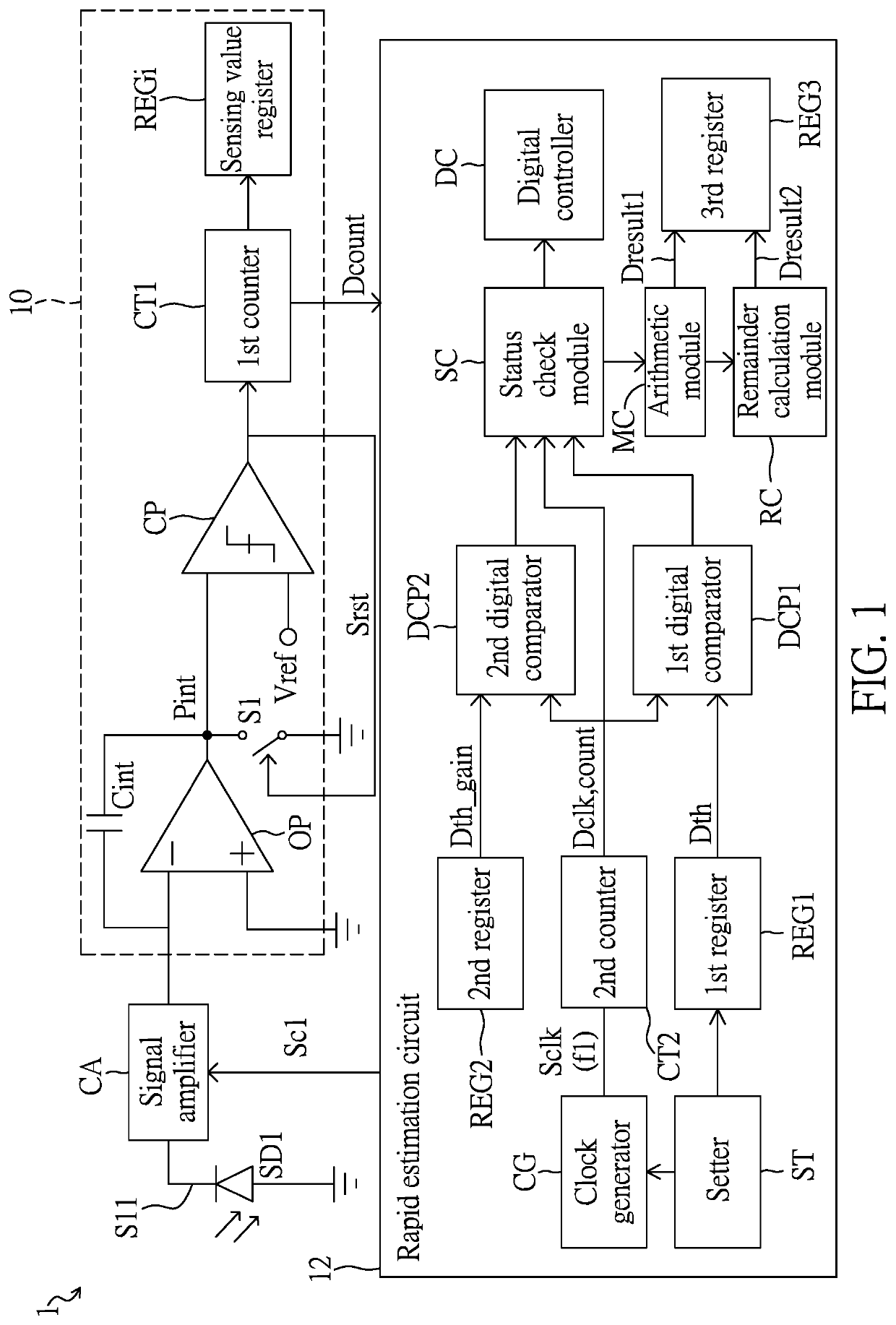
The present invention provides a circuit and method for estimating the value of a sensing signal quickly and accurately. This can save time and money, and improve overall signal resolution. The method uses the change trend density of the signal to estimate the final result, and ensures accuracy by using a higher-frequency signal as the basis of the calculation. This allows for the use of the original sensor's count value result in various applications without breaking the circuit structure, and provides a significant improvement in resolution for weaker input signals.

Problems solved by technology

However, under certain conditions, due to change in external signals are small, speeds at which the original sensing signals reaching the reference voltage value are not much different, but the corresponding digital result needs to be obtained in a complete integration time, resulting in an increase in costs of time.
Furthermore, a resolution of the digital result generated is limited by capabilities of the counter.

Method used


Image

  • Rapid sensing value estimation circuit and method thereof
  • Rapid sensing value estimation circuit and method thereof
  • Rapid sensing value estimation circuit and method thereof

Examples


Embodiment Construction

[0023]The present disclosure is more particularly described in the following examples that are intended as illustrative only since numerous modifications and variations therein will be apparent to those skilled in the art. Like numbers in the drawings indicate like components throughout the views. As used in the description herein and throughout the claims that follow, unless the context clearly dictates otherwise, the meaning of “a”, “an”, and “the” includes plural reference, and the meaning of “in” includes “in” and “on”. Titles or subtitles can be used herein for the convenience of a reader, which shall have no influence on the scope of the present disclosure.

[0024]The terms used herein generally have their ordinary meanings in the art. In the case of conflict, the present document, including any definitions given herein, will prevail. The same thing can be expressed in more than one way. Alternative language and synonyms can be used for any term(s) discussed herein, and no speci...


PUM


Abstract

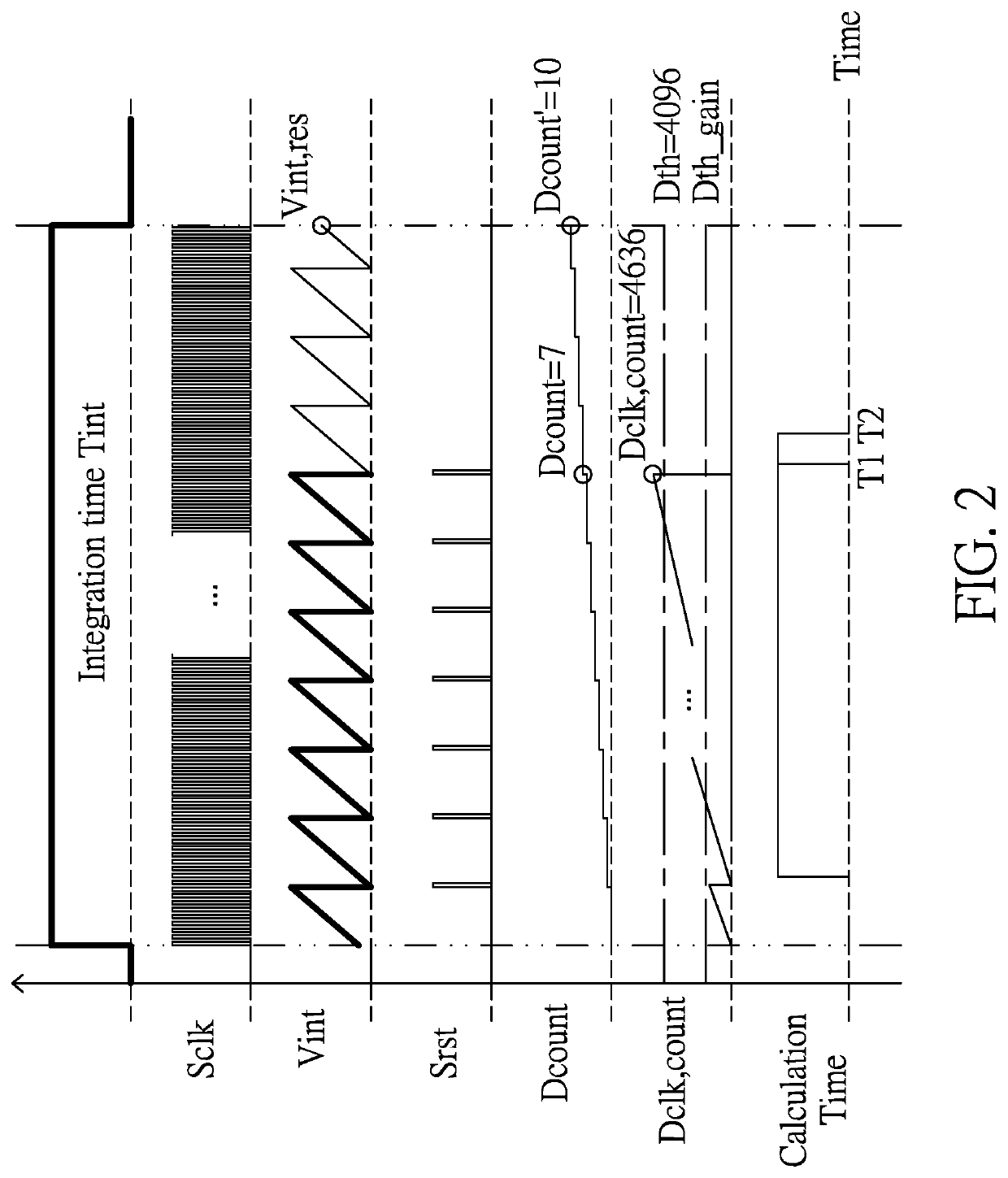
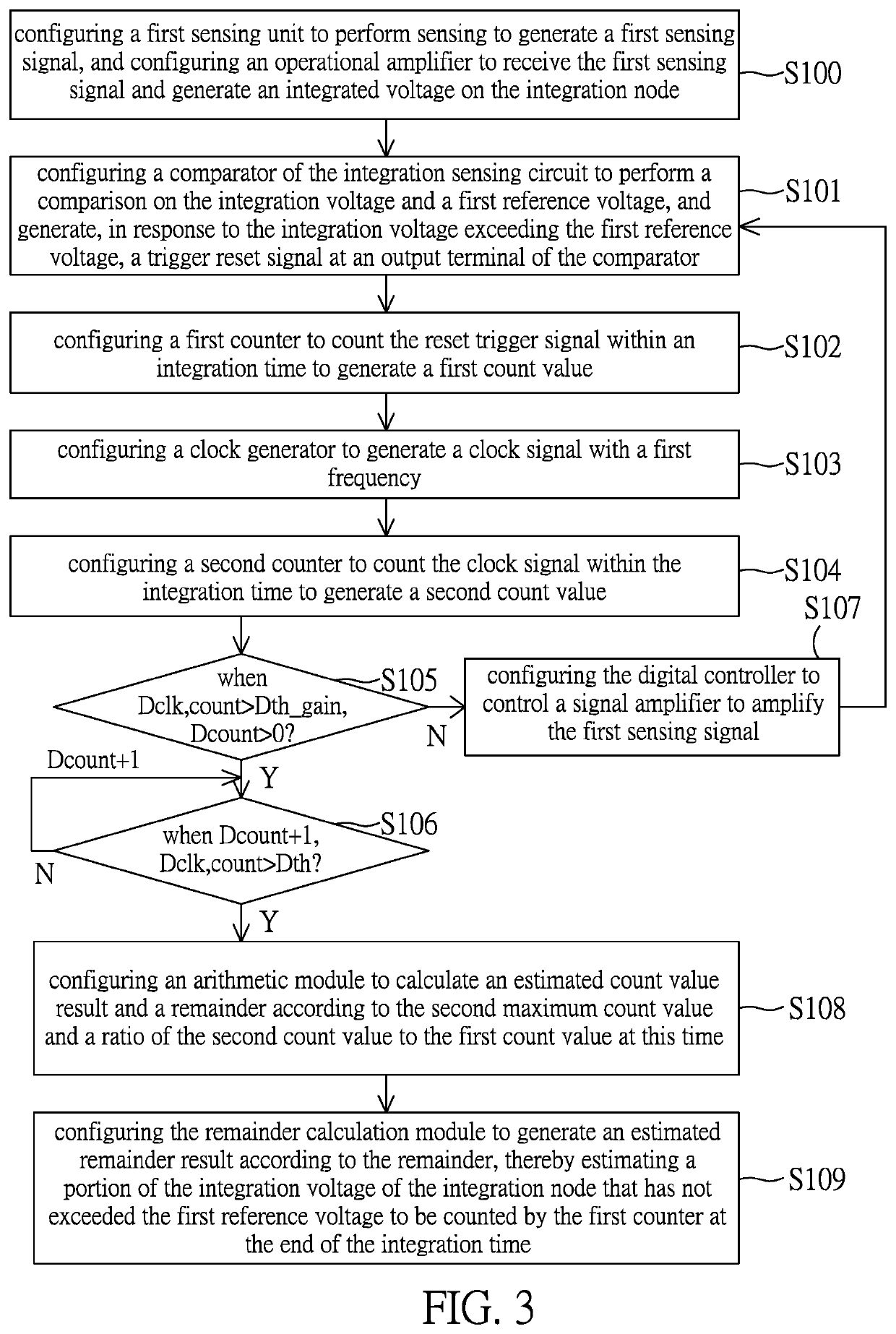
A rapid sensing value estimation circuit and a method thereof are provided. The circuit includes a first sensing unit, an integration sensing circuit and a rapid estimation circuit. The rapid estimation circuit includes a clock generator, a second counter, a first digital comparator, an arithmetic module and a remainder calculation module. The clock generator generates a clock signal with a first frequency. The second counter counts the clock signal within the integration time to generate a second count value. The first digital comparator determines whether the second count value exceeds a first predetermined count value when the first count value increases. The arithmetic module calculates an estimated count value result and a remainder, and the remainder calculation module can further calculate and estimate values of decimal places of this signal based on the remainder.

Description

CROSS-REFERENCE TO RELATED PATENT APPLICATION[0001]This application claims the benefit of priority to Taiwan Patent Application No. 109121625, filed on Jun. 24, 2020. The entire content of the above identified application is incorporated herein by reference.[0002]Some references, which may include patents, patent applications and various publications, may be cited and discussed in the description of this disclosure. The citation and / or discussion of such references is provided merely to clarify the description of the present disclosure and is not an admission that any such reference is “prior art” to the disclosure described herein. All references cited and discussed in this specification are incorporated herein by reference in their entireties and to the same extent as if each reference was individually incorporated by reference.FIELD OF THE DISCLOSURE[0003]The present disclosure relates to rapid sensing value estimation circuit and method thereof, and more particularly to rapid se...

Claims


Application Information

Patent Timeline
Patent Type & Authority Applications(United States)
IPC IPC(8): G01R19/165H03F3/45
CPCG01R19/16576H03F2203/45116H03F2200/129H03F3/45475H03F3/68H03K25/00G06M1/272H03F3/087H03F2203/45512
Inventor HONG, JIA-HUA
Owner ANPEC ELECTRONICS CORPORATION
Learn More