Device and Method for Manufacturing Magnet Embedded Core

Active Publication Date: 2021-12-30
KURODA PRECISION INDS
View PDF1 Cites 0 Cited by
  • Summary
  • Abstract
  • Description
  • Claims
  • Application Information

AI Technical Summary

Benefits of technology

The invention prevents the creation of flash, which can cause failure. This results in a more reliable and efficient device.

Problems solved by technology

Flash deposited on the base may cause a surface flaw in the molded resin or leakage of resin.
As a result, the resin may not be properly charged into the magnet insertion holes.

Method used


Image

  • Device and Method for Manufacturing Magnet Embedded Core
  • Device and Method for Manufacturing Magnet Embedded Core
  • Device and Method for Manufacturing Magnet Embedded Core

Examples


Embodiment Construction

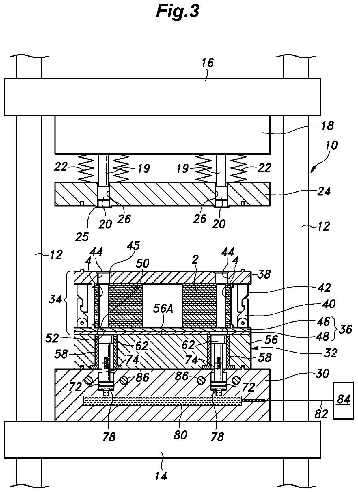
[0027]Preferred embodiments of the present invention are described in the following with reference to the appended drawings.

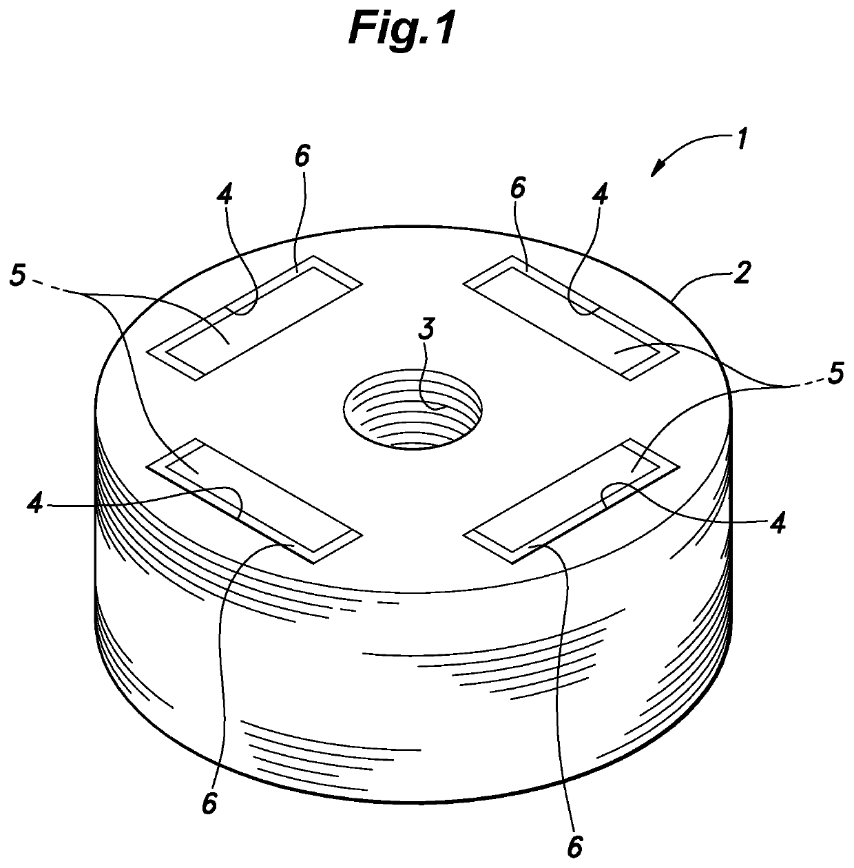
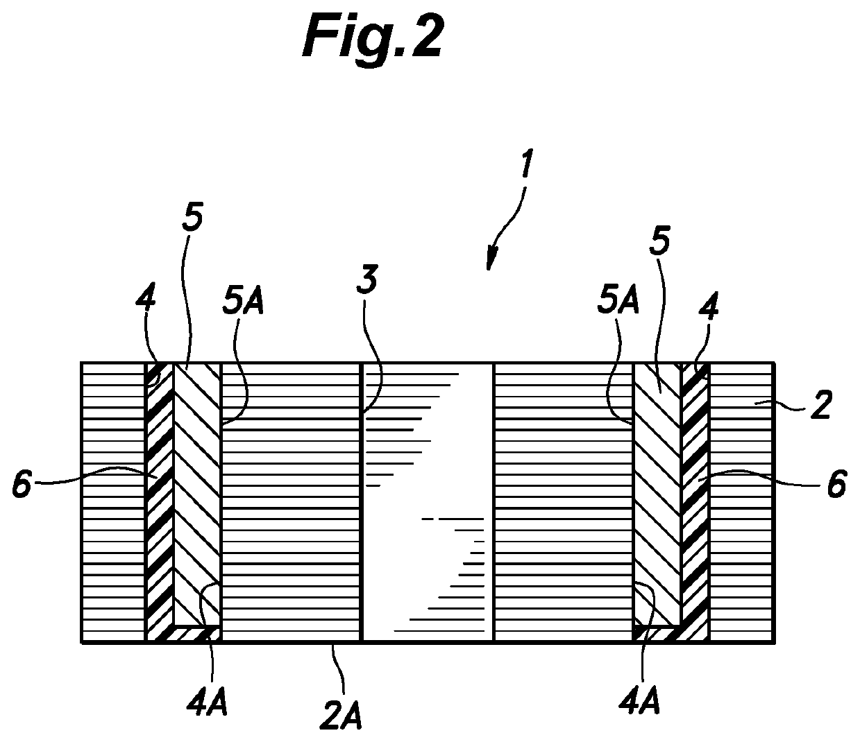
[0028]First of all, an example of the magnet embedded core manufactured by the manufacturing device and the manufacturing method according to the embodiment of the present invention is described in the following with reference to FIGS. 1 and 2.

[0029]The magnet embedded core 1 is a component part of rotating machinery such as an electric motor, and includes a rotor core 2. The rotor core 2 is a laminated iron core formed by laminating a plurality of electromagnetic steel sheets and joining the electromagnetic steel sheets together by using a per se known joining method (such as crimping, laser welding, bonding, etc.). The rotor core 2 is substantially annular in shape in plan view, and is centrally provided with a shaft hole 3.

[0030]The rotor core 2 is formed with a plurality of magnet insertion holes 4 each defining a substantially rectangular space. Each magne...


PUM

PropertyMeasurementUnit
Thicknessaaaaaaaaaa
Thicknessaaaaaaaaaa

Abstract

In manufacturing a magnet embedded core, creation of flash, and problems associated with flash are prevented. A device for manufacturing the magnet embedded core comprises a base (32) comprising an upper surface at which a resin pot chamber (64) for storing molten resin opens, a separator plate (36) detachably placed on the upper surface of the base (32) to support a rotor core (2) thereon and having a gate (50) and a cull opening (52) communicating the magnet insertion hole (4) of the rotor core (2) with the resin pot chamber (64), and a plunger (62) movably provided in the resin pot chamber (64) to press the molten resin in the resin pot chamber (64) into the magnet insertion hole (4) via the gate (50) and the cull opening (52), wherein an annular recess (66) is formed on the upper surface of the base (32) so as to extend outward of the resin pot chamber (64) and communicate with the resin pot chamber (64).

Description

TECHNICAL FIELD[0001]The present invention relates to a device and a method for manufacturing a magnet embedded core, and in particular to a device and a method for manufacturing the magnet embedded core for use in rotating electric machinery.BACKGROUND ART[0002]Various technologies have been developed to manufacture the magnet embedded core of rotating electric machinery by inserting a magnet into each of a plurality of magnet insertion holes defined axially in a rotor core, charging resin material in liquid form into the magnet insertion holes, and curing the charged resin material to fix the magnets in the rotor core.[0003]A known manufacturing device for such a magnet embedded core includes a base provided with resin pot chambers for storing molten resin therein, each having an opening at an upper surface of the base, a separator plate detachably placed on the upper surface of the base to support the rotor core and provided with communication passages communicating the resin pot...

Claims


Application Information

Patent Timeline
IPC IPC(8): H02K15/10H02K15/02B29C45/14B29C45/03B29C45/02
CPCH02K15/10H02K15/02B29L2031/7498B29C45/03B29C45/021B29C45/14344H02K15/03B29K2995/0008B29C45/14778Y02T10/64
Inventor IKEDA, MASANOBUMURAYAMA, TOMOAKI
Owner KURODA PRECISION INDS
Why Eureka
Try Eureka