Pressure Drop Estimation

a pressure drop and estimation technology, applied in the field of pressure drop estimation, can solve the problems of operator dependence and the limited accuracy of this approach, and achieve the effects of improving complexity, improving accuracy, and improving accuracy

Active Publication Date: 2022-01-06
KING'S COLLEGE LONDON
View PDF1 Cites 0 Cited by
  • Summary
  • Abstract
  • Description
  • Claims
  • Application Information

AI Technical Summary

Benefits of technology

[0009]In one embodiment described herein we present a non-invasive semi-automatic method for the estimation of pressure differences based on the work-energy principle, namely the Work-Energy Relative Pressure (WERP) method. The arrangement has benefits of simplicity and computational efficiency, requiring integrations and computations that can be executed directly from the image acquired using 4D PC-MRI or Echocardiography (ECG). Introducing the mathematics behind the method, we detail its application for cardiovascular flow data. In the first...

Problems solved by technology

However, despite its advantages, application of pressure catheterization is limited to specific cohorts of patients due to its intrinsic invasiveness and associated risks and cost.
While useful ...

Method used


Image

  • Pressure Drop Estimation
  • Pressure Drop Estimation
  • Pressure Drop Estimation

Examples


first embodiment

[0036]2. Methods

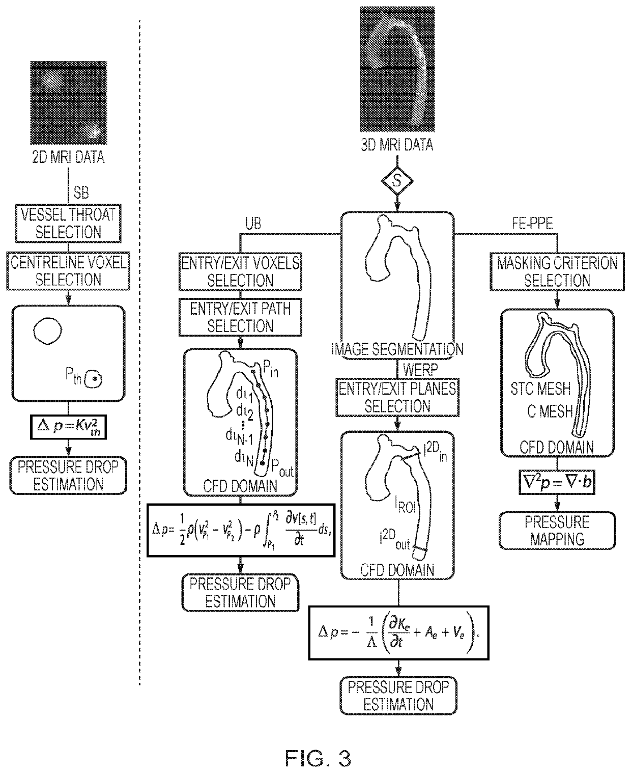
[0037]Starting from the work-energy principle, we derive the formula for the pressure difference over a vascular segment (Section 2.1). Subsequently, we detail its discrete formulation (Section 2.2) and pre-processing steps (Section 2.3) required to work with 4D PC-MRI data.

[0038]2.1. Pressure Difference from Fluid Work Energy

[0039]Pressure differences in a fluid system are related to the kinematics of the flow field. This relationship is described by the well-known Navier-Stokes equations where, in the absence of gravity, variations in pressure are balanced by fluid accelerations and viscous stresses. Using the conservation of mass and momentum for closed systems, the work-energy for an incompressible isothermal Newtonian fluid over a Region Of Interest (ROI) (Ω) with boundary Γ yields,

ρ2⁢∂∂t⁢∫Ω⁢(v·v)⁢⁢dx︸∂∂t⁢Ke+ρ2⁢∫Γ⁢v2⁢(v·n)⁢⁢dx︸Ae+∫Γ⁢pv·n⁢⁢dx︸H⁡(p)-∫Γ⁢μ⁡[D⁡(v)·n]·v⁢⁢dx︸Se+μ2⁢∫Ω⁢D⁡(v)⁢:⁢D⁡(v)⁢⁢dx︸Ve=0,

[0040]where v represents the velocity, ρ the pressure, n is the...

third embodiment

on

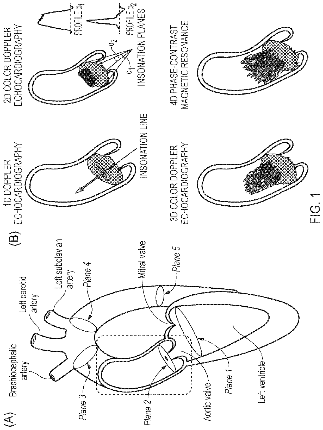
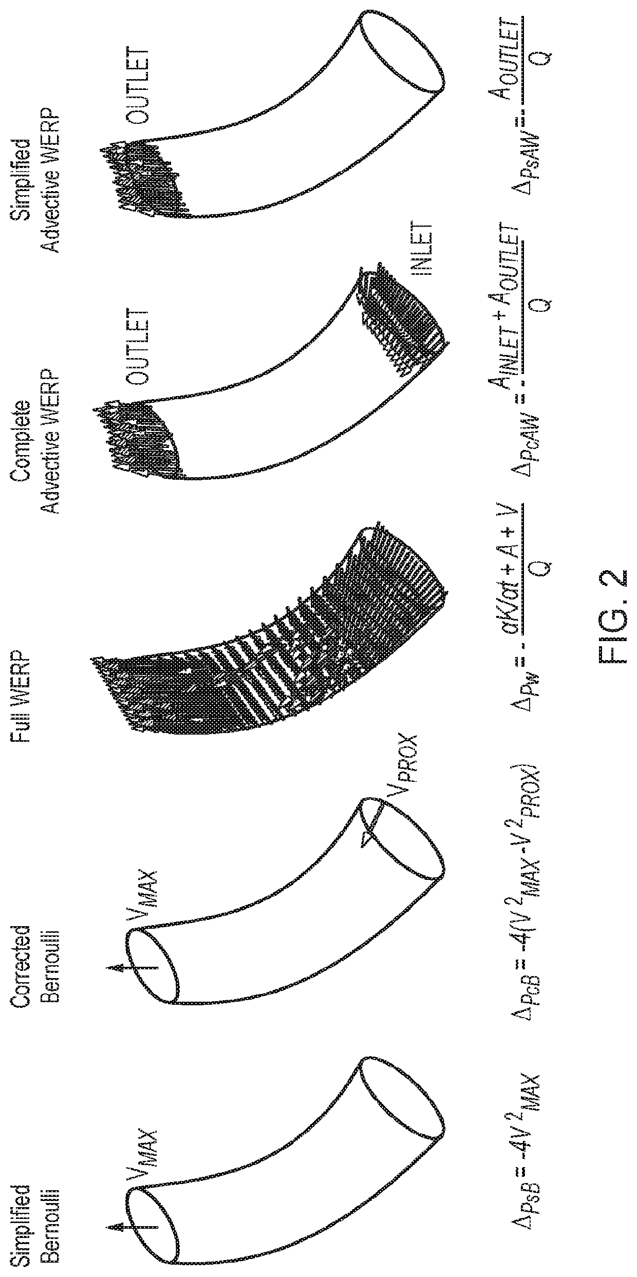
[0142]The third embodiment relates to the simplifed advective WERP approach, which can be performed using 2D Doppler ECG data, although of course it may also be applied with other imaging systems that obtain more information, such as 2D PC MRI, 3D Doppler ECG. In this example, however, FIG. 10(B) shows a 2D Doppler ultrasound ECG equivalent system. Here a transducer 1000 obtains 2D Doppler measurements from the subject, under the control of 2D Doppler ECG system 152, comprising 2D Doppler ECG controller 154. The system produces 2D Doppler ECG data 156, and which is then used as an input to the sAW calculation program 158, which performs the necessary processing as described previously to find solutions for the outlet planes of the vessel being monitored, which is then stored and output as sAW output data 160.

[0143]FIG. 8 illustrates the basic method of operation of the sAW approach. Here, at s.8.2 the ECG data of the outlet plane of the subject vessel for which pressure drop acros...


PUM


Abstract

Embodiments and aspects described herein provide methods and systems for determining pressure difference across a tube arising from fluid flow within the tube, comprising: obtaining three-dimensional time dependent fluid velocity data at a plurality of points along the tube; processing the three-dimensional time dependent fluid velocity data to determine: i) a flow rate (Q) of the fluid through the tube; ii) the kinetic energy (K) of the fluid flow through the tube; iii) an advective energy rate (A) of the fluid flow through the tube; and iv) a viscous dissipation rate (V) pertaining to the fluid flow; and calculating the pressure difference in dependence on all of the flow rate (Q), kinetic energy (K), advective energy rate (A), and viscous dissipation rate (V). Further embodiments are also described.

Description

CROSS-REFERENCE TO RELATED CASES[0001]This application is a continuation of, and claims priority to, U.S. application Ser. No. 16 / 085,258, filed Sep. 14, 2018, entitled “Method and System for Pressure Drop Estimation,” which is a U.S. National Stage application under 35 U.S.C. § 371 of International Application PCT / GB17 / 50694 (published as WO 2017 / 158343 A1), filed Mar. 14, 2017, which claims the benefit of priority to Application GB 1604412.5, filed Mar. 15, 2016. Benefit of the filing date of each of these prior applications is hereby claimed, and each is hereby incorporated by reference in its entirety.TECHNICAL FIELD[0002]The present invention relates to a method and system for estimating the pressure drop through a vessel, and in particular embodiments to the estimation of blood pressure drop through a blood vessel based on measurements of velocity obtained from various medical imaging modalities.[0003]Background to the Invention and Prior Art Pressure drops or differences (als...

Claims


Application Information

Patent Timeline
IPC IPC(8): A61B5/021A61B5/00A61B5/026A61B8/08A61B8/06A61B5/055A61B8/04
CPCA61B5/021A61B5/7242A61B5/0263A61B8/488A61B2576/023A61B5/055A61B8/04A61B8/5223A61B8/06G16H30/40
Inventor LAMATA DE LA ORDEN, PABLONORDSLETTEN, DAVIDDONATI, FABRIZIOSMITH, NICOLAS
Owner KING'S COLLEGE LONDON
Why Eureka
Try Eureka