Apparatus of muscle treatment comprising electrical muscle stimulation electrode and method of muscle treatment using that
- Summary
- Abstract
- Description
- Claims
- Application Information
AI Technical Summary
Benefits of technology
Problems solved by technology
Method used
Image
Examples
first embodiment
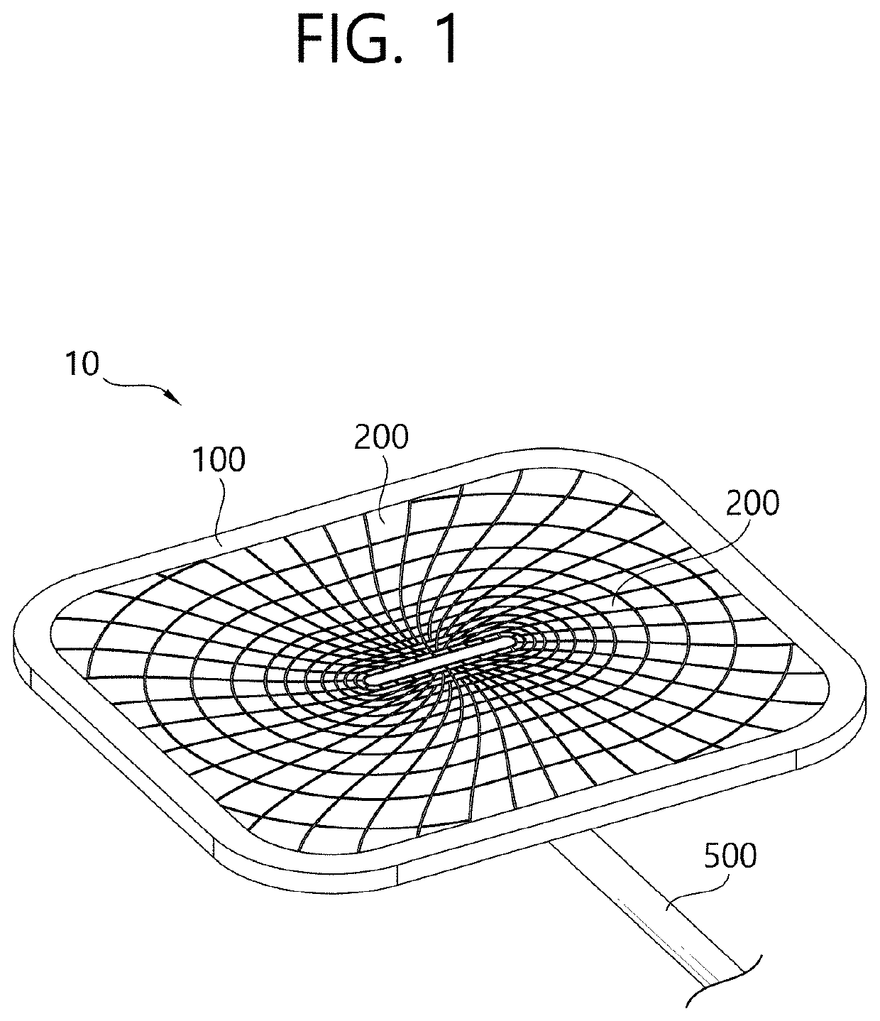
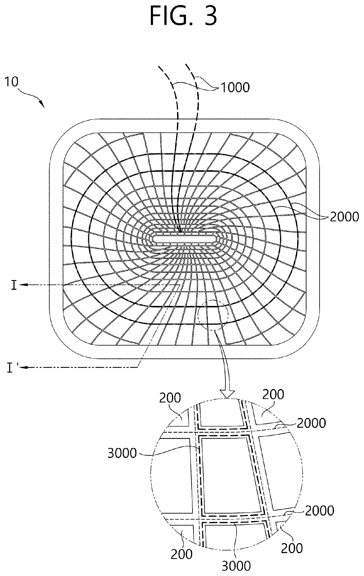
[0072]Hereinafter, a configuration of an electrical muscle stimulation (EMS) pad according to the present invention will be described in detail with reference to FIGS. 1 to 4.
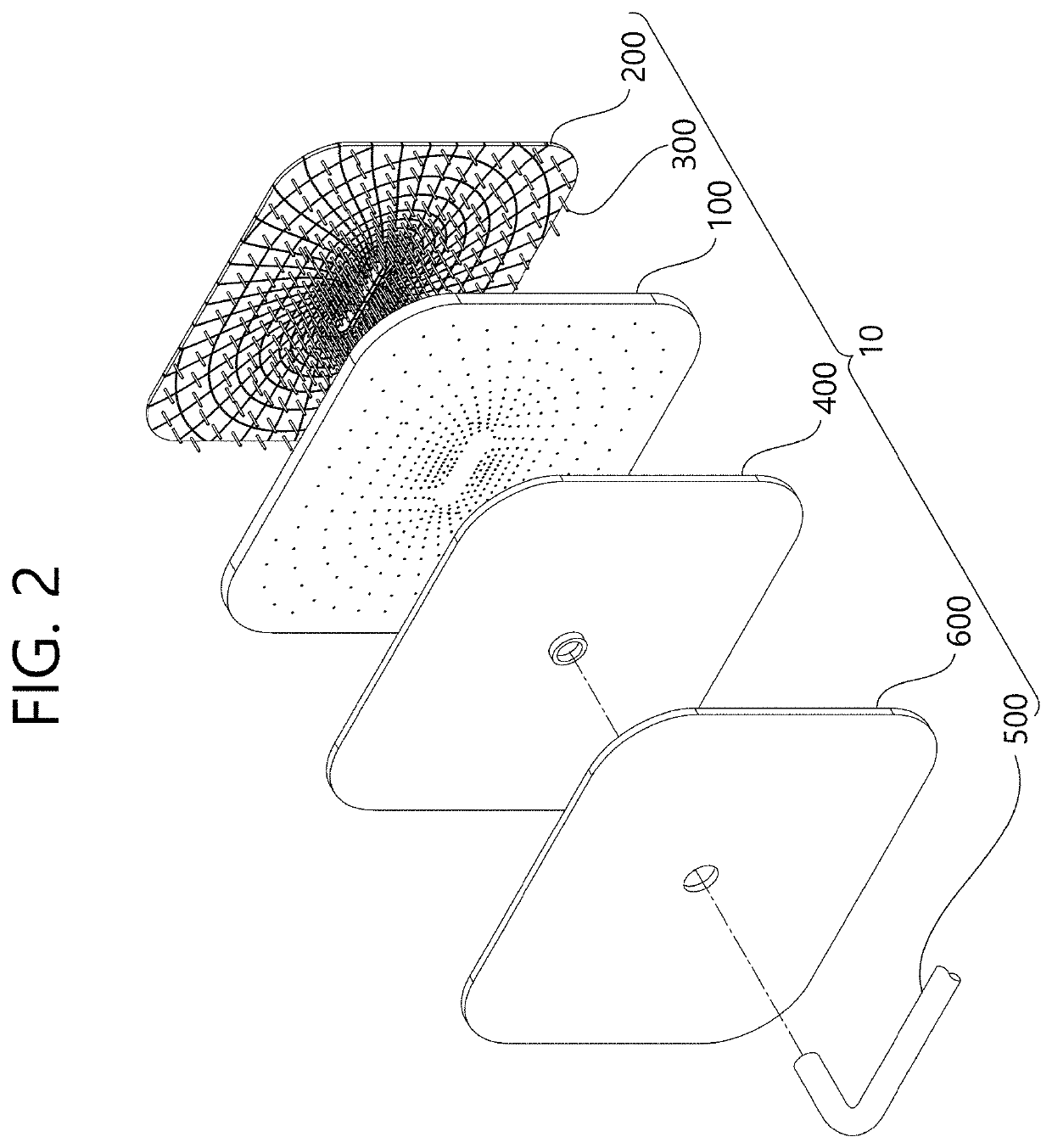
[0073]FIG. 1 is a perspective view showing an electrode pad according to the first embodiment of the present invention, and FIG. 2 is an exploded perspective view of the electrode pad according to the first embodiment of the present invention.
[0074]Referring to FIG. 1, the electrode pad 10 according to the first embodiment of the present invention may be configured to be attached to a skin surface and may receive RF energy from the outside in a state of being attached to the skin and transfer the received RF energy to the skin.
[0075]An electrode pad 10 according to the first embodiment of the present invention may include a base 100, an electrode 200, a first connection portion 300, a second connection portion 400, a shielding layer 600, and a connector 500.
[0076]The base 100 is a base on which the electrode 20...
second embodiment
[0099]Hereinafter, an EMS electrode pad 10 according to the present invention will be described in detail with reference to FIGS. 6 and 8.
[0100]This embodiment may also be configured to include the same components as those of the embodiment described above, and descriptions of the same components will be omitted to avoid redundancy and different components will be described.
[0101]FIG. 6 is a partial cross-sectional view of the electrode pad 10 according to the second embodiment of the present invention. The second embodiment of the present invention may include a dielectric layer 700 covering a plurality of electrodes 200 provided on a lower surface 101 of a base.
[0102]The dielectric layer 700 is formed in a flat plate shape and may be configured to cover a plurality of electrodes 200 at the same time. The dielectric layer 700 may be formed of a material having a dielectric constant in a predetermined range. The dielectric layer 700 may be attached to each of the electrodes 200 such...
third embodiment
[0107]Hereinafter, an electrode pad 10 according to the present invention will be described in detail with reference to FIGS. 9 and 10. This embodiment may also be configured to include the same components as those of the embodiment described above, and descriptions of the same components will be omitted to avoid redundancy and different components will be described.
[0108]FIGS. 9A, 9B and 9C are an enlarged cross-sectional view of the electrode pad 10 according to the third embodiment of the present invention. Referring to FIGS. 9A, 9B and 9C are, the EMS electrode pad 10 according to the third embodiment of the present invention may include a conductive layer 800 covering a plurality of electrodes 200. The conductive layer 800 may be configured to cover the lower surface of the electrode 200. As an example, the conductive layer 800 may be a graphene layer. Since graphene has high electrical conductivity and high elasticity, it may be appropriately deformed according to a curve of t...
PUM
 Abstract
Description
Claims
Application Information
 - R&D
- Intellectual Property
- Life Sciences
- Materials
- Tech Scout
- Unparalleled Data Quality
- Higher Quality Content
- 60% Fewer Hallucinations
Browse by: Latest US Patents, China's latest patents, Technical Efficacy Thesaurus, Application Domain, Technology Topic, Popular Technical Reports.
© 2025 PatSnap. All rights reserved.Legal|Privacy policy|Modern Slavery Act Transparency Statement|Sitemap|About US| Contact US: help@patsnap.com


