Drive unit
- Summary
- Abstract
- Description
- Claims
- Application Information
AI Technical Summary
Benefits of technology
Problems solved by technology
Method used
Image
Examples
modification 1
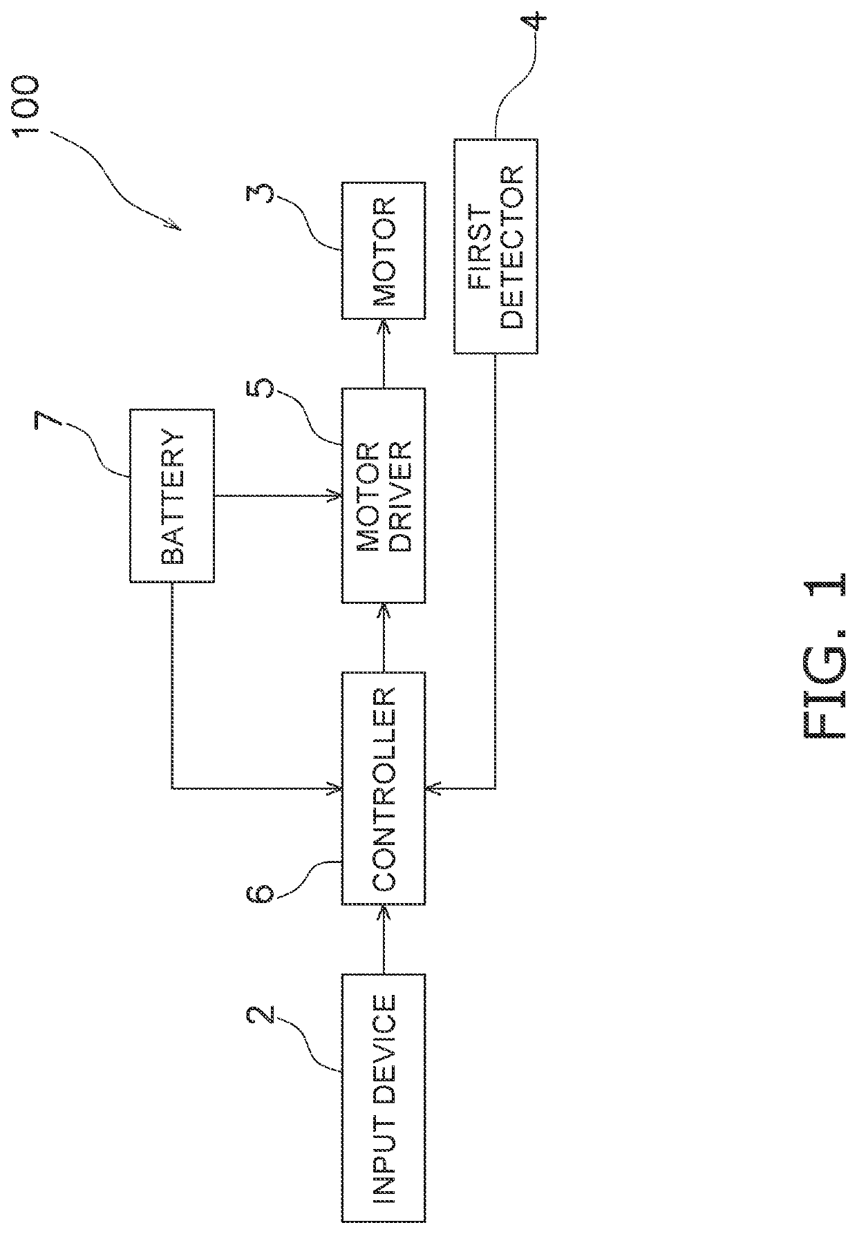
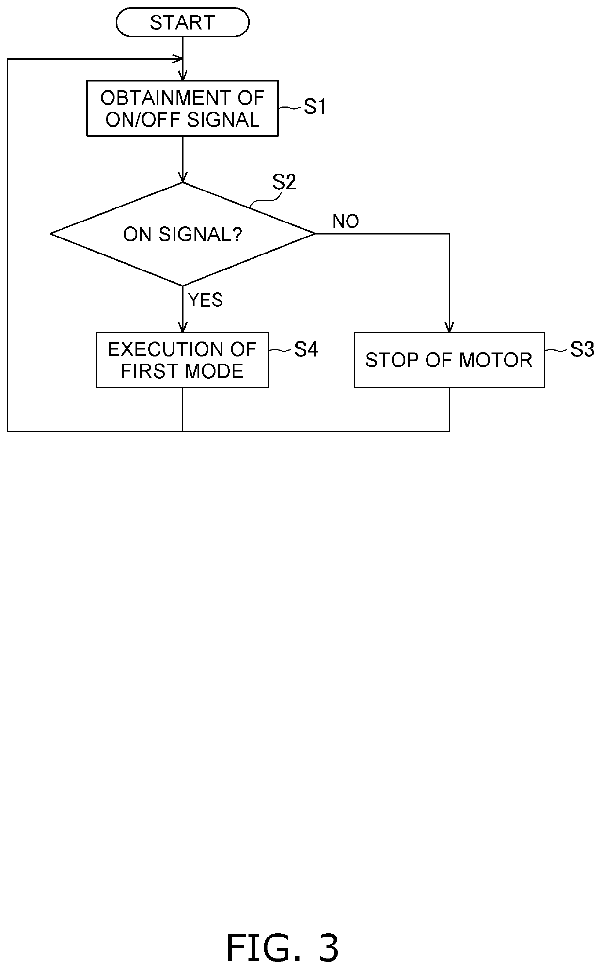
[0051]The controller 6 can selectively execute a first mode and a second mode. A user selects one of a plurality of modes through the input device 2. For example, the user selects one of an off mode, the first mode, and the second mode. When the user operates the input device 2, the input device 2 outputs a mode selection signal to the controller 6. It should be noted that when the off mode is selected, electric driving of the motor 3 is stopped.
[0052]When the user selects the first mode, the controller 6 executes the first mode in a similar manner to the preferred embodiment described above.
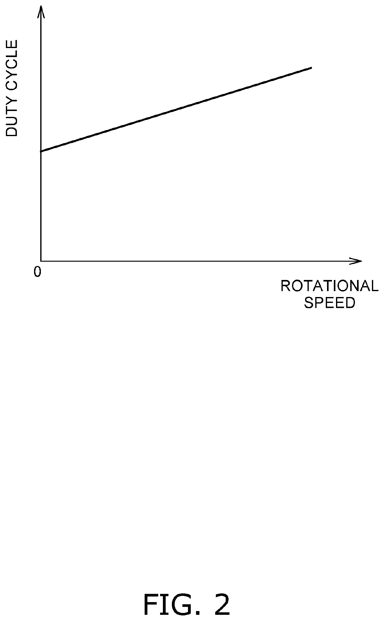
[0053]On the other hand, when the user selects the second mode, the controller 6 executes the second mode. In executing the second mode, the controller 6 performs control of making the duty cycle constant regardless of vehicle speed information. In other words, the controller 6 does not execute such duty cycle computation as done in executing the first mode. The controller 6 outputs a command si...
modification 2
[0060]In the preferred embodiment described above, the controller 6 controls the duty cycle based on only the rotational speed of the motor 3. However, the configuration of the drive unit 100 is not limited to this. For example, as shown in FIG. 7, the drive unit 100 can further include a second detector 8. The second detector 8 is configured to detect the current of the motor 3. The second detector 8 outputs information regarding the detected current of the motor 3 to the controller 6.
[0061]The controller 6 corrects the duty cycle in accordance with the current of the motor 3 detected by the second detector 8. When described in detail, the controller 6 firstly computes the duty cycle in accordance with the rotational speed of the motor 3. Then, the controller 6 corrects the computed duty cycle in accordance with the current of the motor 3.
[0062]For example, the controller 6 is capable of correcting the duty cycle such that the duty cycle increases with reduction in current of the m...
modification 3
[0063]As shown in FIG. 8, the drive unit 100 can further include a third detector 9. The third detector 9 is configured to detect the temperature of the motor 3. The third detector 9 outputs information regarding the detected temperature of the motor 3 to the controller 6.
[0064]The controller 6 corrects the duty cycle in accordance with the temperature of the motor 3 detected by the third detector 9. When described in detail, the controller 6 firstly computes the duty cycle in accordance with the rotational speed of the motor 3. Then, the controller 6 corrects the computed duty cycle in accordance with the temperature of the motor 3.
[0065]For example, the controller 6 is capable of correcting the duty cycle such that the duty cycle reduces with reduction in temperature of the motor 3. Alternatively, the controller 6 can correct the duty cycle such that the duty cycle increases with reduction in temperature of the motor 3.
[0066]Yet alternatively, the controller 6 can correct the duty...
PUM
 Abstract
Description
Claims
Application Information
 - R&D
- Intellectual Property
- Life Sciences
- Materials
- Tech Scout
- Unparalleled Data Quality
- Higher Quality Content
- 60% Fewer Hallucinations
Browse by: Latest US Patents, China's latest patents, Technical Efficacy Thesaurus, Application Domain, Technology Topic, Popular Technical Reports.
© 2025 PatSnap. All rights reserved.Legal|Privacy policy|Modern Slavery Act Transparency Statement|Sitemap|About US| Contact US: help@patsnap.com


