

System and method for air injection passageway integration and optimization in turbomachinery
a turbomachinery and air injection technology, applied in the direction of machines/engines, stators, mechanical apparatuses, etc., to achieve the effect of reducing stator pressure loss, reducing stator airfoil boundary layer growth, and reducing pressure losses and flow deviation
- Summary
- Abstract
- Description
- Claims
- Application Information
AI Technical Summary
Benefits of technology
Problems solved by technology
Method used
Image

Examples
Embodiment Construction
[0026]The following detailed description is merely exemplary in nature and is not intended to limit the invention or the application and uses of the invention. As used herein, the word “exemplary” means “serving as an example, instance, or illustration.” Thus, any embodiment described herein as “exemplary” is not necessarily to be construed as preferred or advantageous over other embodiments. All of the embodiments described herein are exemplary embodiments provided to enable persons skilled in the art to make or use the invention and not to limit the scope of the invention which is defined by the claims. Furthermore, there is no intention to be bound by any expressed or implied theory presented in the preceding technical field, background, brief summary, or the following detailed description.
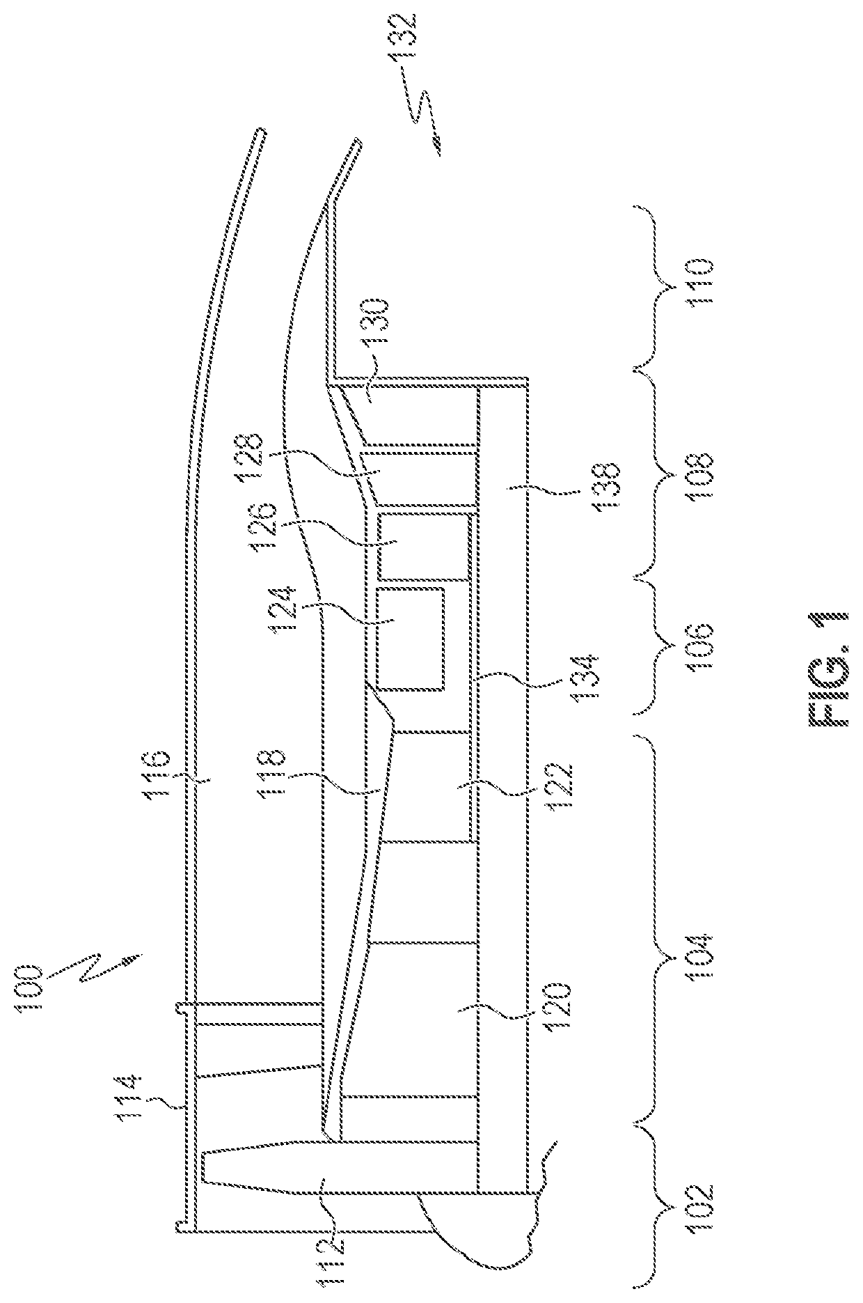
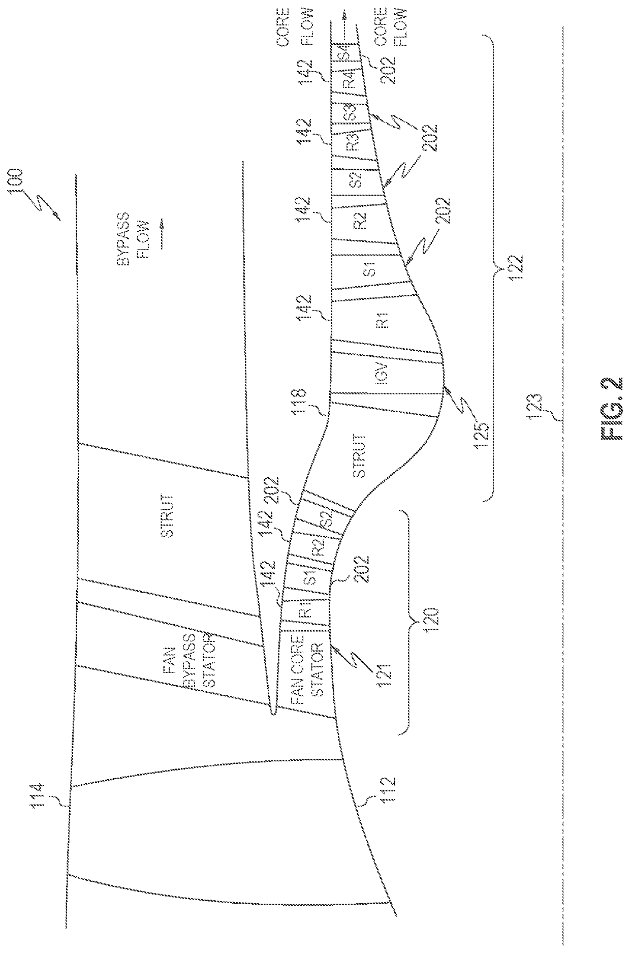
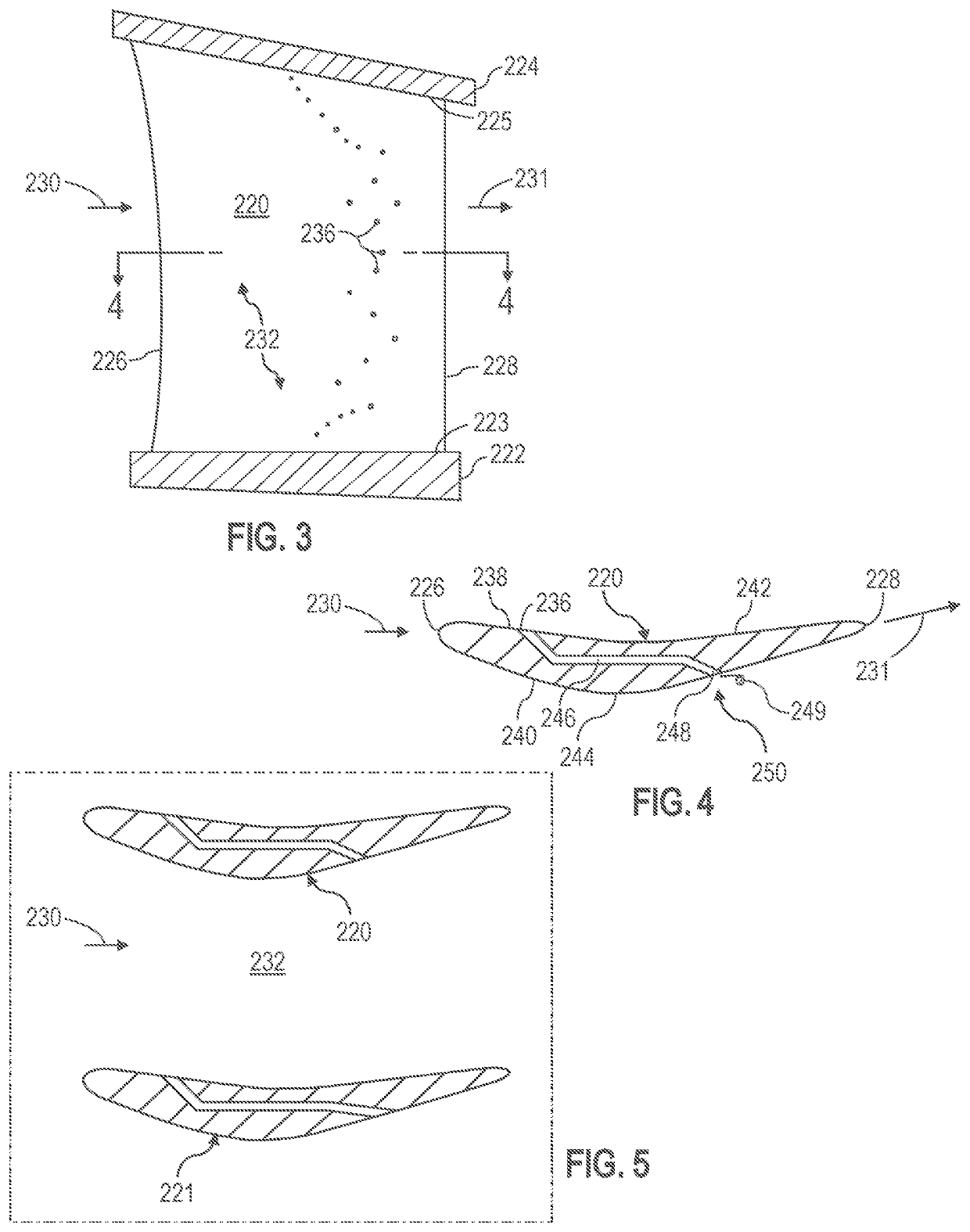
[0027]Various embodiments disclosed herein are directed to specifically designed integrated passageways and their locations that optimize airflow as it is influenced by an airfoil. In a number ...
PUM
 Abstract
Description
Claims
Application Information