Panel with vertical assembly for producing a covering

a vertical assembly and floor covering technology, applied in the field of floor or wall coverings, can solve the problems of slow process of manufacturing complementary dovetail coupling means, inconvenient solution, and detrimental to the overall aesthetics of the floor covering, and achieve the effect of satisfying aesthetics, good locking effect, and optimal resistance to horizontal disassembly

Pending Publication Date: 2022-01-27
GERFLOR
View PDF10 Cites 3 Cited by
  • Summary
  • Abstract
  • Description
  • Claims
  • Application Information

AI Technical Summary

Benefits of technology

[0015]One of the objectives of the present invention is then to overcome the above-mentioned disadvantages by offering a vertically assembled panel for producing a covering, which has an optimal resistance to the horizontal disassembly, in particular to resist the passage of heavy loads, while presenting a good locking effect, as well as a satisfying aesthetic.

Problems solved by technology

This solution is not appropriate because the installation becomes long and complex.
However, the process of manufacturing the complementary dovetail coupling means is slow, as it is done by die-cutting.
In addition, the complementary coupling means are visible on the surface of the panel, which is detrimental to the overall floor covering's aesthetic.

Method used


Image

  • Panel with vertical assembly for producing a covering
  • Panel with vertical assembly for producing a covering
  • Panel with vertical assembly for producing a covering

Examples


first embodiment

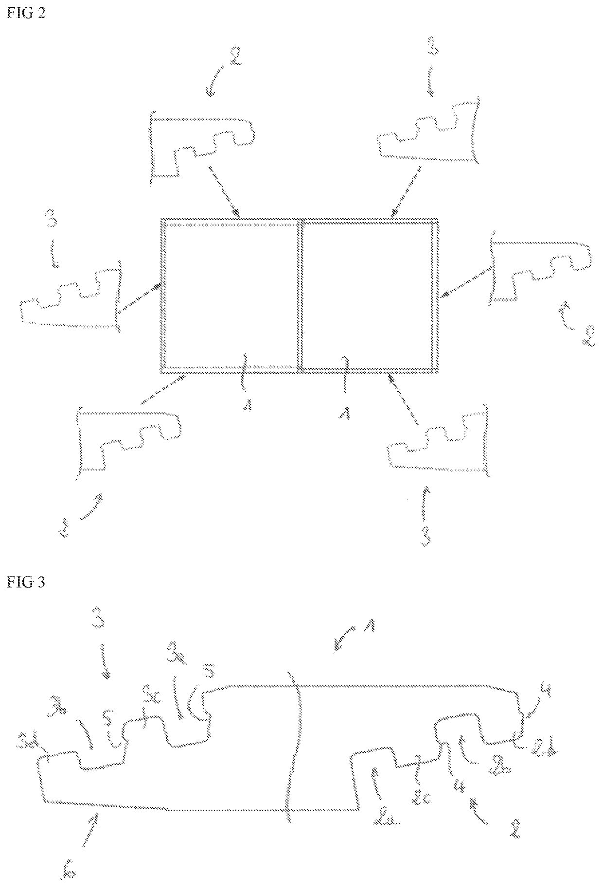
[0059]Therefore, illustrated in FIG. 3, the male coupling means (2) comprise a lug (4) provided on the outer wall of the male inner stud (2c), and a lug (4) provided on the outer wall of the male outer stud (2d) and, complementarily, the female coupling means (3) comprises a notch (5) provided on an outer wall of the female inner stud (3c), and a notch (5) provided on an inner wall of the female inner groove (3a).

second embodiment

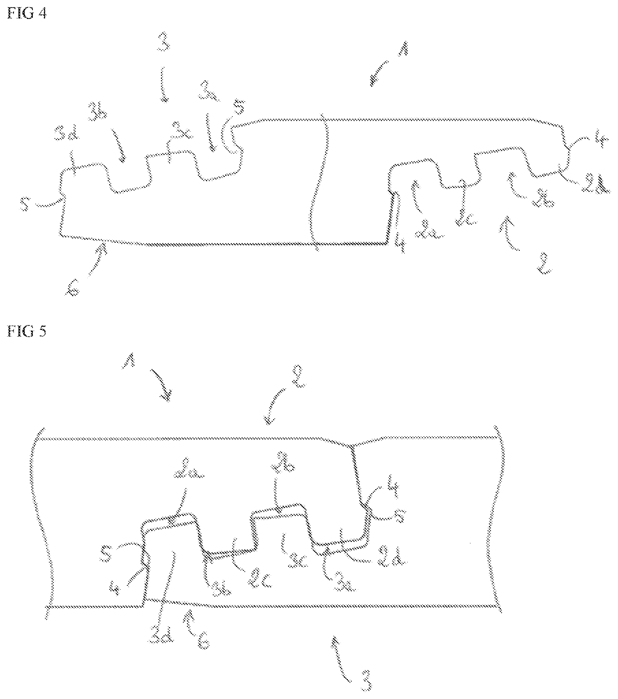
[0060]In a second embodiment as shown in FIG. 4, the male coupling means (2) comprises a lug (4) provided on the outer wall of the male outer stud (2d), and a lug (4) provided on the inner wall of the male inner groove (2a) and, complementarily, the female coupling means (3) comprises a notch (5) provided on an inner wall of the female inner groove (3a), and a notch (5) provided on an outer wall of the female outer stud (3d).

[0061]Of course, other embodiments can be considered with different notch (5) / lugs (4) combinations, without exceeding the scope of the invention.

[0062]According to another characteristic of the invention, the female external stud (3d) comprises a chamfered portion (6) at the level of the bottom face of the panel (1) and forming an angle comprised between 2° and 20° with the bottom face of the panel (1). Thus, during the assembly of the two adjacent panels (1), the chamfered portion (6) allows the lowering of the external female stud (3d) to come, by deformation...


PUM

PropertyMeasurementUnit
angleaaaaaaaaaa
angleaaaaaaaaaa
angleaaaaaaaaaa

Abstract

A panel (1) having a blade or slab shape, preferably made of a plastic material for producing a floor or wall covering, said panel (1) comprising two pairs of opposite sides defining four edges, two edges of which comprise male coupling means (2), and two edges comprise complementary female coupling means (3), the kinematics of assembling of two adjacent panels (1) being vertical, characterized in that:
    • the male coupling means (2) comprise two parallel grooves extending along the edge and opening onto a bottom face of the panel (1), so as to define an internal male groove (2a), an external male groove (2b), an internal male stud (2c), and an external male stud (2d);
    • the female coupling means (3) comprise two parallel grooves extending along the edge and opening on an upper face of the panel (1), so as to define a female internal groove (3a), a female external groove (3b), a female internal stud (3c), and a female external stud (3d);
    • the male coupling means (2) comprise two lugs (4) and/or notches (5) and the female coupling means (3) comprise two complementary notches (5) and/or lugs (4) forming, after assembly of two adjacent panels (1), stoppers against a vertical displacement between two assembled adjacent panels (1).

Description

TECHNICAL FIELD[0001]The present invention relates to the field of floor or wall coverings, and more specifically to a polyvinyl chloride panel in blade or slab shape for producing of such coverings.[0002]Generally speaking, this type of panel has two pairs of opposite sides which define four edges, two of which comprise male coupling means, and two of which comprise complementary female coupling means, in order to assemble two adjacent panels according to a vertical kinematics.PRIOR ART[0003]In the field of floor or wall coverings, it is well known to use panels which include complementary male and female coupling means.[0004]For example, according to document WO2016 / 030 627, on behalf of the applicant, a floor panel for producing a covering comprises:[0005]male coupling means made of a so-called proximal groove intended to open onto a bottom face of the panel, and of a flexible distal tab intended to extend at one end of an edge of the panel towards the bottom face thereof;[0006]f...

Claims


Application Information

Patent Timeline
Patent Type & Authority Applications(United States)
IPC IPC(8): E04F15/02E04F15/10E04F13/08
CPCE04F15/02038E04F15/105E04F2201/043E04F2201/0138E04F2201/042E04F13/0894
Inventor CARPENTIER, FABIENWENGRYN, MICHEL
Owner GERFLOR
Why Eureka
Try Eureka