Vehicle air conditioning

a technology for air conditioning systems and vehicles, applied in vehicle components, vehicle heating/cooling devices, transportation and packaging, etc., can solve the problems of reducing the amount of work required by the peltier device, heating or cooling the cabin environment, etc., to reduce localised hot or cold regions, reduce the effect of air exchang

Pending Publication Date: 2022-02-03
DYSON TECH LTD
View PDF6 Cites 0 Cited by
  • Summary
  • Abstract
  • Description
  • Claims
  • Application Information

AI Technical Summary

Benefits of technology

[0023]Locating the inlets adjacently has the result that the first and second airflows are drawn from the same region of the passenger cabin. This tends to result in a lower pressure region in the vicinity of the inlets, and consequently establishes a movement of air within the passenger cabin towards the lower pressure region and the inlets of the ducts. This movement of air towards the inlets is advantageous firstly for mixing air inside the passenger cabin, thereby improving the temperature uniformity of the cabin environment and reducing localised hot or cold regions. Further, the flow of air within the passenger cabin towards the inlets of the ducts tends to result in a less turbulent influent airflow through each inlet. This effect has been observed to be most pronounced where the inlets are immediately adjacent or closely spaced, in particular, where the inlets are separated by a distance of less than 10 centimetres. Furthermore, because the ducts draw air from the same region of the passenger cabin, the temperature and/or density of the influent air flows will tend to be similar. Supplying the first and second blowers with air having approximately the same temperature and density has the advantage that audible noise generated by the airflows will tend to be in the same frequency range.
[0024]The vehicle may comprise a door to the passenger cabin, the door comprising a compartment, and the second airflow may be discharged into the compartment. Discharging the second airflow directly to atmosphere has the disadvantage that atmospheric turbulence and pressure variation induced as the vehicle travels at speed may result in undesirable aerodynamic effects on the second airflow as it passes across the one or more blowers or the Peltier device. For example, atmospheric turbulence may result in buffeting of the second airflow, which could cause damage to the one or more blowers and/or result in blower ‘chatter’ producing audible noise. In comparison, walls of the door at least partly enclose the compartment, thus restricting air exchange between the compartment and atmosphere. Consequently, speed induced aerodynamic effects such as air turbulence may be relatively lesser in the compartment than in the atmosphere surrounding the vehicle. As a result, the second airflow may be less negatively affected by undesirable aerodynamic effects when discharged into the compartment.
[0025]The compartment may comprise a vent for discharging the second airflow from the compartment to atmosphere. In other words, the compartment may be vented to atmosphere via a vent. This arrangement has the advantage that air can be discharged from the compartment to atmosphere. Consequently, a sustained flow of air may be established from the air conditioning system through the compartment of the door to atmosphere. In other words, venting the compartment to atmosphere allows the second airflow to be discharged to atmosphere through the compartment. Preferably the vent may be relatively small in size in order to reduce backflow of air through the vent from the atmosphere into the compartment is relatively low. This arrangement has the advantage that turbulent atmospheric air is inhibited from entering the compartment. As a result turbulence within the compartment is minimised. Preferably the vent aperture has a maximum diameter dimension of less than 2 centimetre (cm), preferably less than 1.5 cm, more preferably no greater than 1 cm. Preferably the cross-sectional area of the vent aperture is less than 4 square centimetres (cm2), preferably less than 2.5 cm2, more preferably no greater than 1 cm2. The compartment may comprise a plurality of such vents for discharging the second airflow to atmosphere. Preferably the aggregate tot...

Problems solved by technology

The first airflow is discharged to the passenger compartment and may thus heat or cool the cabin environment.
Thus, drawing the first airflow from t...

Method used


Image

  • Vehicle air conditioning
  • Vehicle air conditioning
  • Vehicle air conditioning

Examples


Embodiment Construction

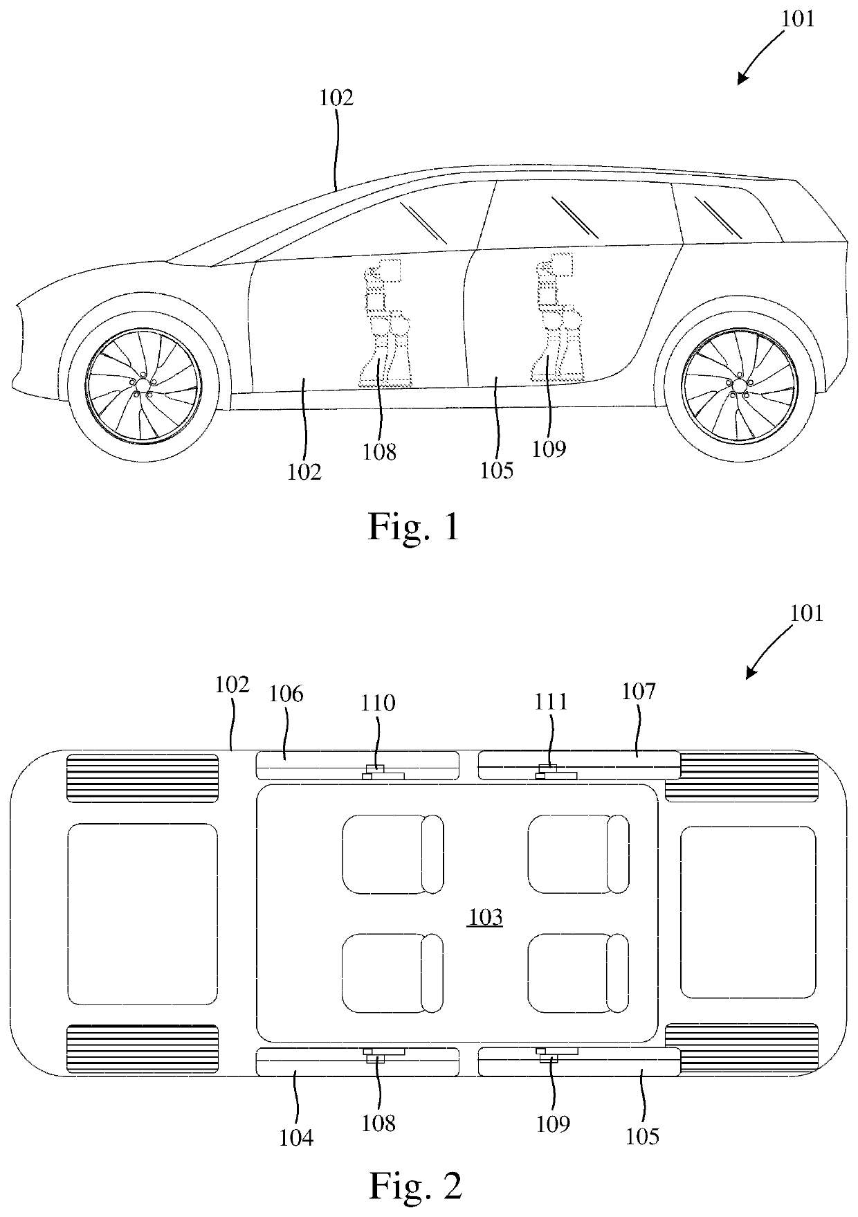
[0039]Referring firstly to FIGS. 1 and 2, a vehicle, which in the example takes the form of a passenger car 101, comprises a body structure 102 defining a passenger cabin 103 for accommodating passengers, door openings in the side of the body structure 102 to permit passenger ingress and egress from the cabin 103, and a plurality of doors 104, 105, 106, 107, hingedly connected to the body structure 102 adjacent a respective door opening to selectively close the door opening.

[0040]The car 101 further comprises a plurality of air conditioning systems, 108, 109, 110, 111, for heating or cooling air supplied to the passenger cabin 103. Each of the air conditioning systems 108 to 111 is mounted to a respective door 104 to 107 and includes an inlet and an outlet open to the passenger cabin 103. In the way that will be described further with reference to FIG. 10, each of the air conditioning systems 108 to 111 is operable to draw air from the passenger cabin 103, selectively heat or cool t...


PUM


Abstract

A vehicle comprising a passenger cabin and an air conditioning system is disclosed. The air conditioning system comprises a Peltier device, a first blower for directing a first airflow over a first side of the Peltier device, and a second blower for directing a second airflow over a second side of the Peltier device. The second blower draws the second airflow from inside the passenger cabin, and the second airflow is discharged to outside the passenger cabin.

Description

REFERENCE TO RELATED APPLICATIONS[0001]This application is a national stage application under 35 USC 371 of International Application No. PCT / GB2019 / 052675, filed Sep. 24, 2019, which claims the priority of United Kingdom Application No. 1815862.6, filed Sep. 28, 2018, the entire contents of each of which is incorporated herein by reference.FIELD OF THE DISCLOSURE[0002]The present invention relates to a vehicle with an air conditioning system for heating or cooling air supplied to the cabin of the vehicle.BACKGROUND OF THE DISCLOSURE[0003]Vehicles, such as passenger cars, often include an air conditioning system for heating, cooling or dehumidifying air supplied to the passenger cabin. Such systems typically comprise a heating element, a cooling element, and a motor driven fan to blow air over the heating / cooling elements into the passenger cabin. It is desirable to improve the performance and the noise-vibration-harshness (NVH) characteristics of vehicle air conditioning systems in...

Claims


Application Information

Patent Timeline
IPC IPC(8): B60H1/00B60H3/06
CPCB60H1/00478B60H2001/00221B60H3/0641B60H1/243B60H1/00207
Inventor WOODFIELD, DANIEL JAMESFERREIRA, ROSS PATRICKPETERS, LAURENT JAMESPOULTON, ROY EDWARD
Owner DYSON TECH LTD
Why Eureka
Try Eureka