Driving device
- Summary
- Abstract
- Description
- Claims
- Application Information
AI Technical Summary
Benefits of technology
Problems solved by technology
Method used
Image

Examples
first embodiment
[0024]A first embodiment of the present disclosure will be described with reference to FIGS. 1 to 4B. Note that the embodiment described below shows a preferred concrete example on performing the present disclosure. There are some parts that specifically show various technical matters that are technically preferable, but the technical scope of the present disclosure is not limited to such a concrete example.
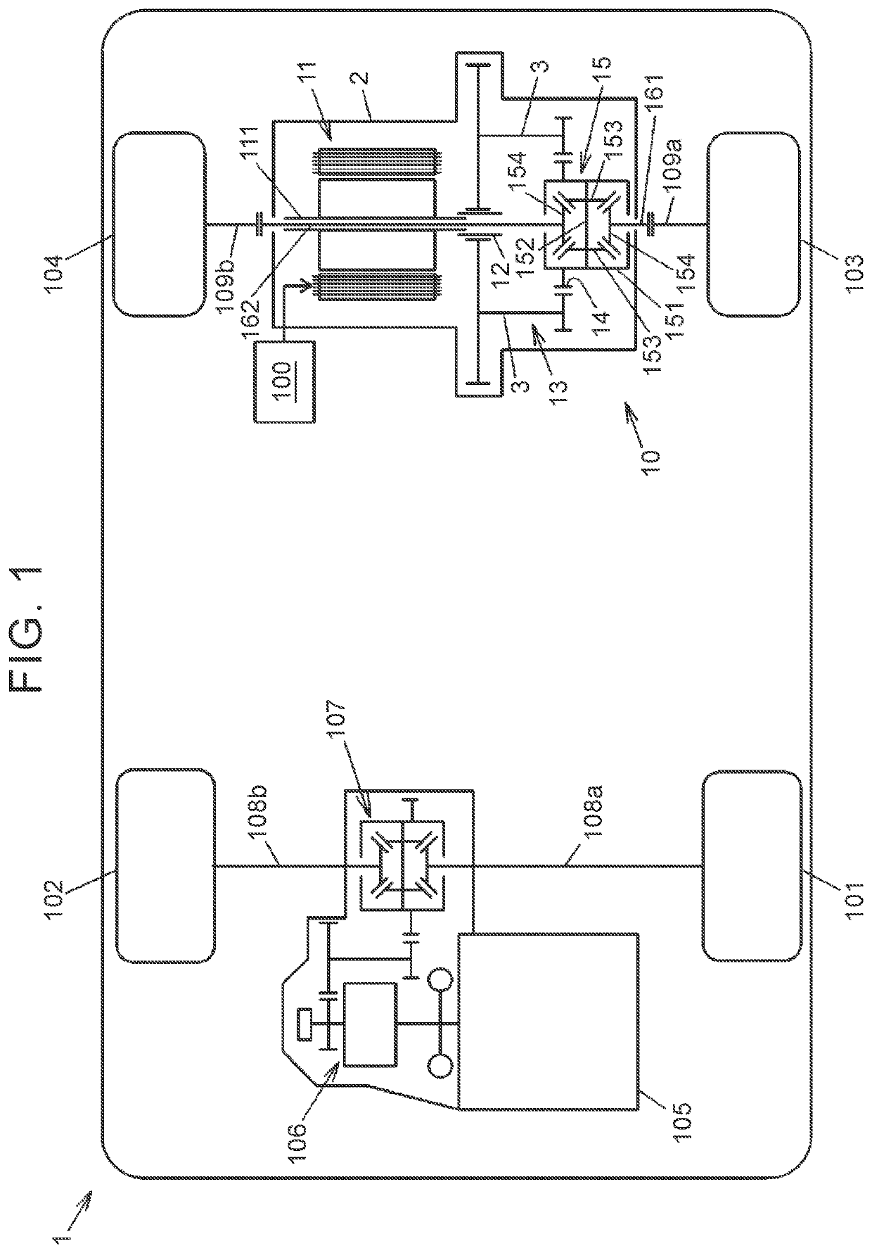
[0025]FIG. 1 is a schematic view illustrating a schematic exemplary configuration of a vehicle provided with a driving device according to the first embodiment of the present disclosure. The vehicle 1 is a four-wheel drive vehicle that can drive right and left front wheels 102, 101 and right and left rear wheels 104, 103. The right and left front wheels 102, 101 are driven by an engine 105 as a main drive source, and the right and left rear wheels 104, 103 are driven by a driving device 10 including an electric motor 11 as an auxiliary drive source. The electric motor 11 of the d...
second embodiment
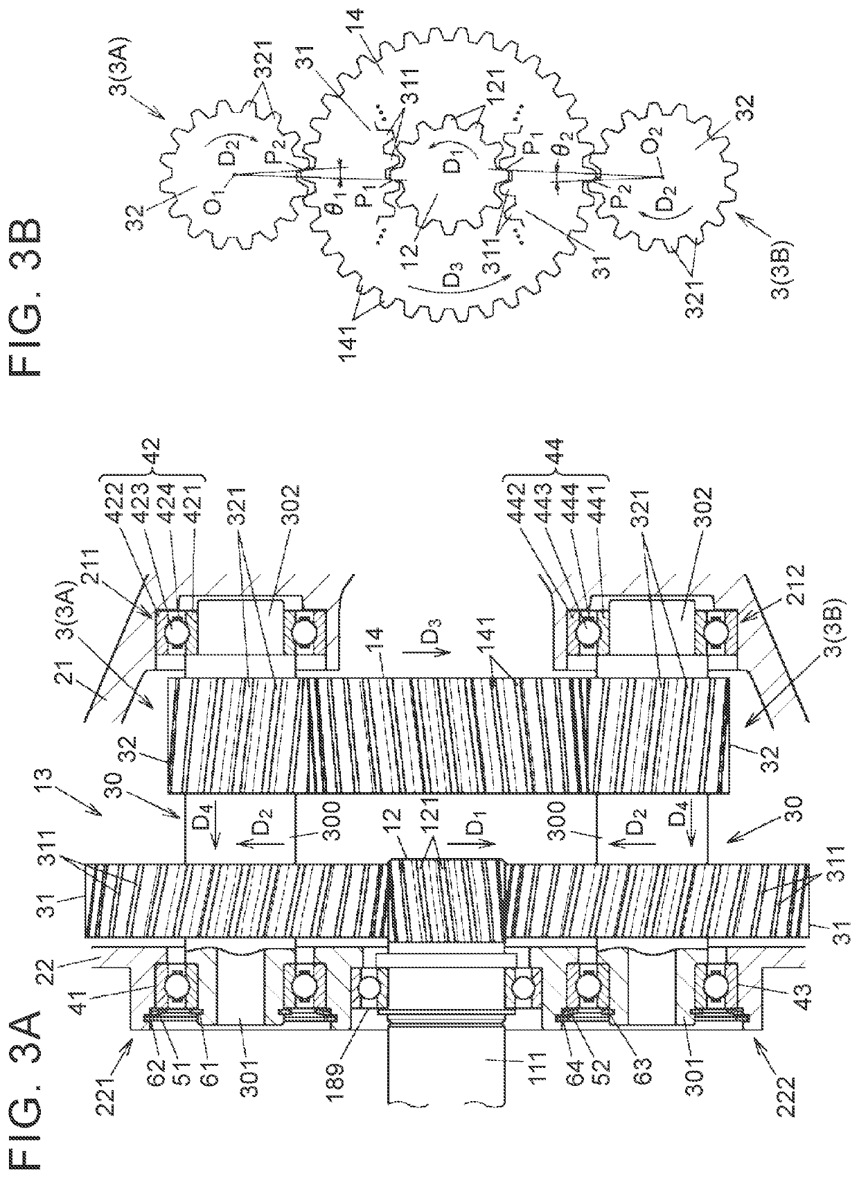
[0063]Next will be described a second embodiment of the present disclosure with reference to FIGS. 5A, 5B, 5C. FIG. 5A is a configuration diagram illustrating the drive gear 12, the deceleration mechanism 13, and the driven gear 14 in the second embodiment together with a section of part of the first housing member 21 and the second housing member 22. FIG. 5B is a partial enlarged view of FIG. 5A and illustrates the first bearing 41 and its peripheral part in an enlarged manner. FIG. 5C is a partial enlarged view of FIG. 5A and illustrates the third bearing 43 and its peripheral part in an enlarged manner. In FIGS. 5A to 5C, constituents common to those described in the first embodiment have the same reference signs used in FIGS. 3A, 3B, and redundant descriptions are omitted.
[0064]As illustrated in FIG. 5A, in the present embodiment, twisting directions of the flank lines of the external teeth 121, 311, 321, 141 of the drive gear 12, the large-diameter gear wheels 31 and the small-...
third embodiment
[0067]Next will be described a third embodiment of the present disclosure with reference to FIGS. 6A, 6B, 6C. FIG. 6A is a configuration diagram illustrating the drive gear 12, the deceleration mechanism 13, and the driven gear 14 in the third embodiment together with a section of part of the first housing member 21 and the second housing member 22. FIG. 6B is a partial enlarged view of FIG. 6A and illustrates the second bearing 42 and its peripheral part in an enlarged manner. FIG. 6C is a partial enlarged view of FIG. 6A and illustrates the fourth bearing 44 and its peripheral part in an enlarged manner. In FIGS. 6A to 6C, constituents common to those described in the first embodiment have the same reference signs used in FIGS. 3A, 3B, and redundant descriptions are omitted.
[0068]The first and second embodiments deal with a case where the coned disc springs 51 to 54 are placed for the first bearing 41 and the third bearing 43. However, the third embodiment and a fourth embodiment ...
PUM
 Abstract
Description
Claims
Application Information
 - R&D Engineer
- R&D Manager
- IP Professional
- Industry Leading Data Capabilities
- Powerful AI technology
- Patent DNA Extraction
Browse by: Latest US Patents, China's latest patents, Technical Efficacy Thesaurus, Application Domain, Technology Topic.
© 2024 PatSnap. All rights reserved.Legal|Privacy policy|Modern Slavery Act Transparency Statement|Sitemap