Unlock instant, AI-driven research and patent intelligence for your innovation.

High-voltage pulse generator and communication method therefor

Active Publication Date: 2022-02-10
SUZHOU POWERSITE ELECTRIC CO LTD
View PDF0 Cites 0 Cited by
  • Summary
  • Abstract
  • Description
  • Claims
  • Application Information

AI Technical Summary

Benefits of technology

The present application provides a high-voltage pulse generator and a communication method to solve problems of data conflict, slow data transmission speed, occupying controller pin resources, and high cost in the prior art. The communication method allows for faster transmission of data with higher real-time performance using a single transmission line and reducing the number of types of data transmitted during each instance. This results in reduced costs and avoids the issue of data conflict.

Problems solved by technology

This method is often prone to data conflict, for example, when there are two types of data need to occupy the line for transmission at the same time, one of the data must be ignored (This can cause a failure by losing critical data), or one of the two types of data must be delayed to be transmitted (Because high-voltage pulse transmitters have particularly high requirements for real time performance, this delay will cause the final pulse waveform to be unsatisfactory).
Since there are many types of data to be transmitted between the master controller and the sub-controllers, but the control system of the high-voltage generator has different real time requirements for different types of data, the data communication method of method 2 will cause the data transmission speed with high real time requirements to be too slow, which leads to the unsatisfactory final pulse waveform.
This method needs to maintain multiple transmission lines between the master controller and the sub-controllers, occupying the controller pin resources, and each line must ensure its transmission reliability, and the cost is relatively high.

Method used


Image

  • High-voltage pulse generator and communication method therefor
  • High-voltage pulse generator and communication method therefor
  • High-voltage pulse generator and communication method therefor

Examples


embodiment 1

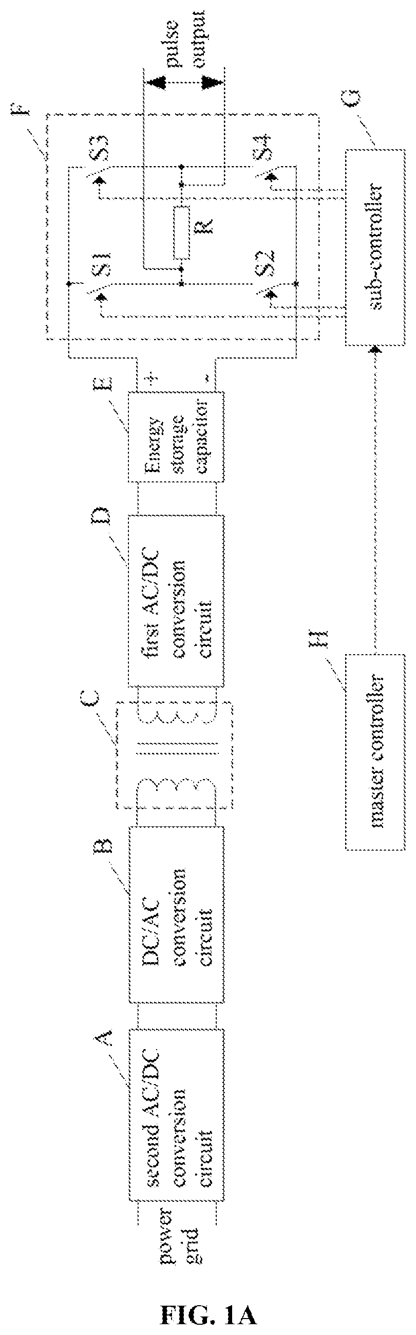
[0028]FIG. 3 shows a flow chart of a communication method for a high-voltage pulse generator according to an embodiment of the present application. Wherein, the high-voltage pulse generator comprises a master controller and a sub-controller, as shown in FIG. 1A. This method can be used by the master controller to transmit data to the sub-controller, and it can also be used by the sub-controller to transmit data to the master controller. Data transmitted between the master controller and the sub-controller comprise a first class of data and a second class of data, and the second class of data at least comprise two types, the high-voltage pulse generator has higher requirements for real time performance of the first class of data than the second class of data. As shown in FIG. 3, the communication method comprises the following steps:

[0029]S101: During a present instance of transmitting the first class of data, transmitting partial types of the second class of data;

[0030]S102: During ...

embodiment 2

[0035]FIG. 4 shows a flow chart of another communication method for a high-voltage pulse generator according to an embodiment of the present application. Wherein, the high-voltage pulse generator comprises a master controller and a sub-controller; data transmitted between the master controller and the sub-controller comprise a first class of data and a second class of data, and the second class of data at least comprise two types, the high-voltage pulse generator has higher requirements for real time performance of the first class of data than the second class of data. As shown in FIG. 4, the communication method comprises the following steps:

[0036]S201: During a present instance of transmission, transmitting a data packet which comprises a first class of data and partial types of the second class of data.

[0037]S201: During a next instance of transmission, transmitting a data packet which comprises a first class of data and some other types of the second class of data; and repeatedl...

embodiment 3

[0043]FIG. 5 shows a flow chart of another communication method for a high-voltage pulse generator according to an embodiment of the present application. Wherein, the high-voltage pulse generator comprises a master controller and a sub-controller, as shown in FIG. 1A.

[0044]This method can be used by the master controller to transmit data to the sub-controller, and it can also be used by the sub-controller to transmit data to the master controller. Data transmitted between the master controller and the sub-controller at least comprise a first class of data and a second class of data, and the second class of data at least comprise two types, the high-voltage pulse generator has higher requirements for real time performance of the first class of data than the second class of data. As shown in FIG. 5, the communication method comprises the following steps:

[0045]S301: During a present instance of receiving the first class of data, receiving partial types of the second class of data;

[0046...


PUM


Abstract

Disclosed are a high-voltage pulse generator and a communication method therefor. The high-voltage pulse generator comprises a master controller and a sub-controller. Data transmitted between the master controller and the sub-controller at least comprise a first class of data and a second class of data, and, the second class of data at least comprise two types. The communication method comprises the following steps: during the present instance of transmitting a first class of data, transmitting partial types of a second class of data; during the next instance of transmitting the first class of data, transmitting other types of second class of data; and repeatedly executing the step until the transmission of all types of second class of data is completed. The present application ensures an increased real time performance in the transmission of the first class of data; moreover, controller pin resources occupied are reduced, costs are reduced, and the problem of data conflict is avoided.

Description

TECHNICAL FIELD[0001]The present application relates to the technical field of high-voltage pulse generators, and in particular to a high-voltage pulse generator and a communication method therefor.BACKGROUND[0002]High-voltage pulse technology refers to the rapid release of energy after a relatively long time of storage, thus producing high-voltage pulses. Energy storage capacitors and voltage control circuits are necessary components of high-voltage pulse generators, after other circuits have stored energy for a long time on the energy storage capacitor, the voltage control circuit controls the discharge of the energy storage capacitors to obtain voltage pulses. A voltage control circuit usually consists of a number of controllable switches (such as MOSFETs) to form a control circuit in the form of an H-bridge, etc., and these controllable switches are controlled by the sub-controller corresponding to the voltage control circuit. The high-voltage pulse generator usually also includ...

Claims


Application Information

Patent Timeline
IPC IPC(8): H04B3/06H03K3/01
CPCH04B3/06H03K3/01H03K3/53H04L5/0064H04L5/0044
Inventor FAN, SHENGFANGCHEN, XIAOSENCHEN, FEIHAO, JIANWEIWANG, WANQUAN
Owner SUZHOU POWERSITE ELECTRIC CO LTD