Positive current collector, positive electrode plate, battery, and apparatus

a current collector and positive electrode technology, applied in the field of electrochemical devices, can solve the problems of secondary batteries, prone to short circuits, smoking, igniting, or even exploding batteries, etc., and achieve the effects of significantly reducing the risk of internal short circuits in the battery, increasing the weight and increasing the energy density of the battery

Pending Publication Date: 2022-02-17
CONTEMPORARY AMPEREX TECH CO
View PDF0 Cites 0 Cited by
  • Summary
  • Abstract
  • Description
  • Claims
  • Application Information

AI Technical Summary

Benefits of technology

[0008]The positive current collector provided in the present application includes a conductive layer having a smaller thickness which is arranged on at least one surface of the support layer, which is beneficial to increasing the weight energy density of the battery. Especially, when the battery undergoes abnormal conditions such as nail penetration, burrs generated on the conductive layer would be greatly reduced as compared with the existing metal current collector, thereby reducing the probability that the burrs on the conductive layer pierce separator to contact with the counter electrode. As a result, the risk of internal short circuit in the battery is significantly reduced. Moreover, in the positive current collector, the support layer has a resistivity greater than that of the conductive layer. Accordingly, the battery would have a larger short-circuit resistance when an internal short-circuit occurs. Hence, short-circuit current and thus short-circuit heat generation are reduced, and further, the nail penetration safety performance of the battery is improved. In addition, when the positive current collector has a tensile strain of 3% or more, the conductive layer has a sheet resistance growth rate T≥50%. Therefore, when the battery undergoes abnormal conditions such as nail penetration, the short-circui

Problems solved by technology

However, the secondary batteries, when undergoing abnormal conditions such as nail penetration, are liable to be short circuited.
In the case of short circuit, a large current together wi

Method used


Image

  • Positive current collector, positive electrode plate, battery, and apparatus
  • Positive current collector, positive electrode plate, battery, and apparatus
  • Positive current collector, positive electrode plate, battery, and apparatus

Examples


examples

[0142]The disclosure of the present application is described in more details through the following examples, which are only for illustrative purpose, because it is apparent to a person of ordinary skill in the art that various modifications and changes could be made within the scope of the disclosure of the present application. Unless otherwise stated, all parts, percentages, and ratios reported in the examples below are based on weight, all the reagents used in the examples are commercially available or synthesized according to conventional methods and can be directly used without further treatment, and all the instruments used in the examples are commercially available.

[0143]Preparation

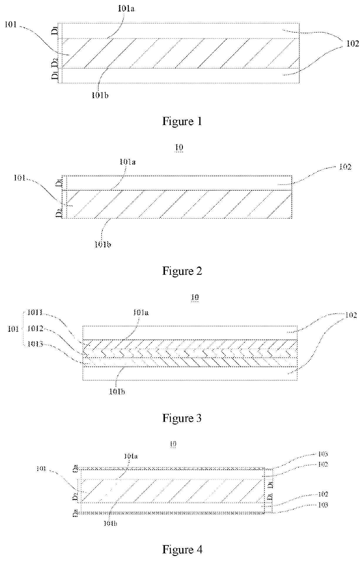
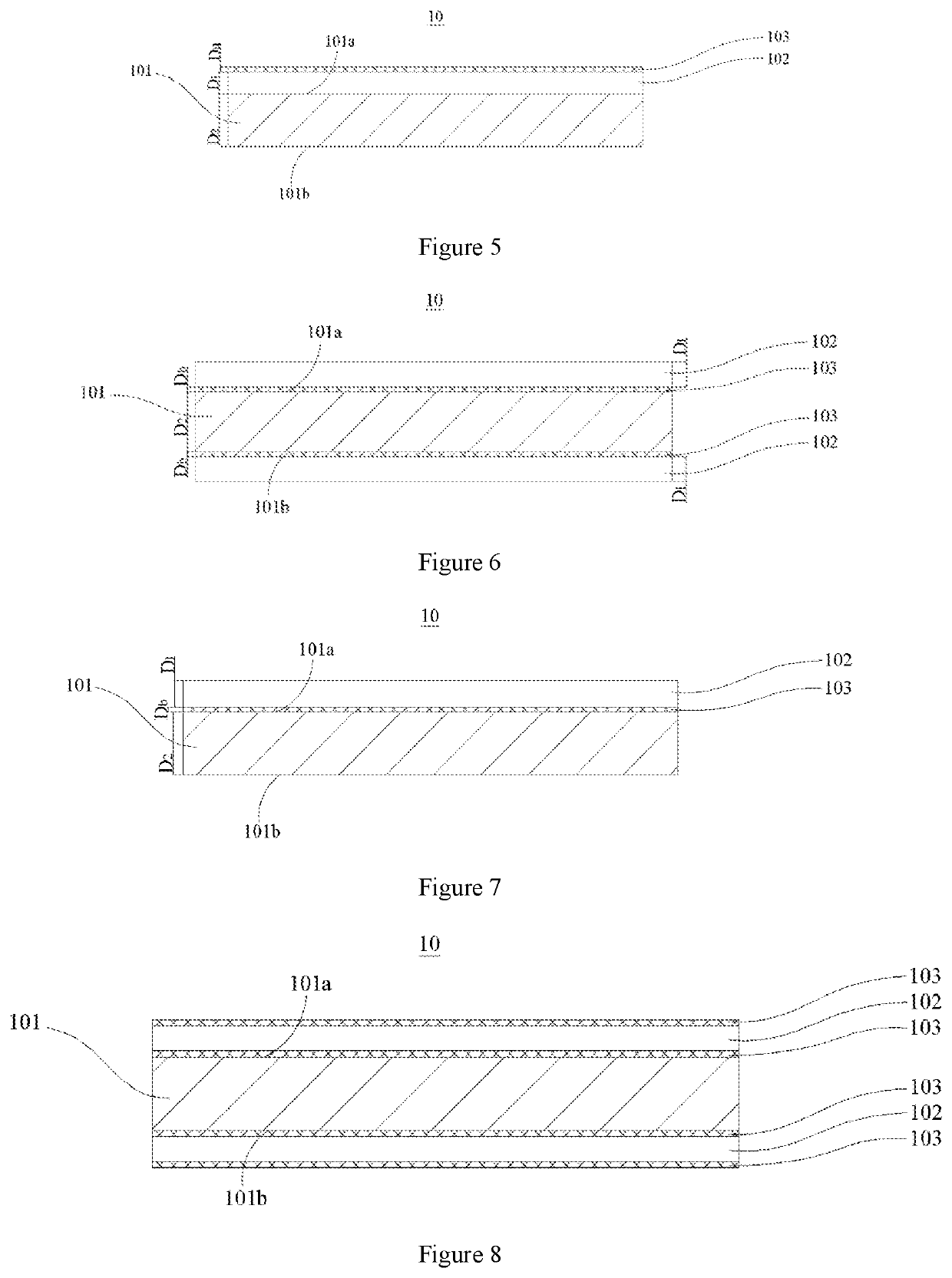
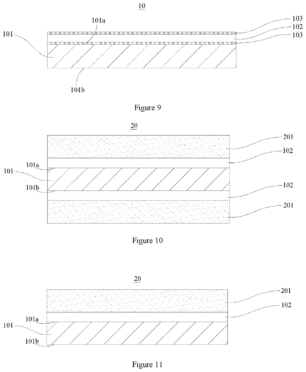
[0144]Preparation of Positive Current Collector

[0145]A support layer having a predetermined thickness was selected to be subjected to surface cleaning treatment. The support layer after the surface cleaning treatment was placed in a vacuum plating chamber. The high-purity aluminum wire in the metal ...


PUM


Abstract

A positive current collector, a positive electrode plate, a battery, and an apparatus, the positive current collector comprising a support layer, provided with two opposite surfaces in a thickness direction of the support layer, and a conductive layer arranged on at least one of the two surfaces of the support layer, wherein the conductive layer has a thickness Di satisfying 300 nm≤D1≤2 μm; and when the positive current collector has a the tensile strain of 3.0% or more, the conductive layer has a sheet resistance growth rate of T1≥50%. The positive current collector has higher safety performance and meanwhile higher electrical performance, and thus a positive electrode plate and a battery adopting the positive current collector could have higher safety performance and meanwhile higher electro-chemical performance.

Description

CROSS-REFERENCE TO RELATED APPLICATION[0001]This application is a continuation of International Application No. PCT / CN2019 / 124825, filed on Dec. 12, 2019, which claims priority to Chinese Patent Application No. 201910351364.7, filed on Apr. 28, 2019, both of which are incorporated herein by reference in their entireties.TECHNICAL FIELD[0002]This application belongs to the technical field of electrochemical devices, and specifically relates to a positive current collector, a positive electrode plate, a battery and an apparatus.BACKGROUND[0003]Secondary batteries represented by lithium ion secondary batteries are widely used in electric vehicles and consumer electronic products due to their advantages of high energy density, high output power, long cycle life and low environmental pollution. However, the secondary batteries, when undergoing abnormal conditions such as nail penetration, are liable to be short circuited. In the case of short circuit, a large current together with a larg...

Claims


Application Information

Patent Timeline
IPC IPC(8): H01M4/66H01M4/134
CPCH01M4/667H01M2004/028H01M2220/20H01M4/134H01M10/0525H01M4/661H01M4/668
Inventor LIANG, CHENGDUHUANG, HUAFENGHUANG, QISEN
Owner CONTEMPORARY AMPEREX TECH CO
Why Eureka
Try Eureka