Cylinder head for an internal combustion engine

a technology of internal combustion engine and cylinder head, which is applied in the direction of combustion engine, cylinder, charge feed system, etc., can solve the problems of combustion residue formation, unwanted increase in emissions, etc., and achieves good flow of propellant gas, facilitates flow transfer passage, and high mechanical stability of the cylinder head

Active Publication Date: 2022-02-24
GE JENBACHER
View PDF42 Cites 3 Cited by
  • Summary
  • Abstract
  • Description
  • Claims
  • Application Information

AI Technical Summary

Benefits of technology

[0016]The provision of a flow transfer passage of such a length and such a cross-sectional area that the issuing propellant gas forms a gas cushion in the flow transfer passage, ensures at least in the first portion of the flow transfer passage that combustion residues do not settle in the form of deposits at the peripheral surface or the formation of such deposits is at least reduced. Possible deposits which nonetheless are formed at the peripheral surface of the flow transfer passage can be entrained by the through flow in the flow transfer passage by virtue of a subsequent expansion phase in the combustion cycle (in which the highest speeds in the through flow in the flow transfer passage occur, at least in the second portion of the flow transfer passage), and thus the flow transfer passage can be cleaned.
[0017]In addition, combustion within the flow transfer passage is prevented by the gas cushion consisting of propellant gas as the gas cushion comprises almost pure propellant gas and cannot be ignited due to the absence of oxygen. The gas cushion formed in that way from propellant gas forms so-to-speak a combustion barrier in the flow transfer passage. In other words the geometrical configuration of the flow transfer passage uses the propellant gas which is already present to prevent the creation of deposits in the flow transfer passage near the prechamber gas valve by not allowing combustion.
[0027]It can preferably be provided that the flow transfer passage, preferably the first portion, has a portion inclined substantially relative to a separation plane between the prechamber and the rest of the cylinder head. In that case, for example, it can be provided that the angle of the flow transfer passage, preferably of first portion, is 20° to 70° with the axis of symmetry of the prechamber gas valve. Such an inclined configuration (at least of the first portion) of the flow transfer passage makes it possible to achieve particularly high mechanical stability for the cylinder head. The fluidic flow configuration of the supplied propellant gas is optimized by virtue of the fact that it does not have to flow through any acute angles. For the production of such a gas passage, it can be provided that a flank of the cylinder head is arranged inclinedly. That, for example, can be so selected that the inclined flank is at a right angle to the axis of the flow transfer passage. That facilitates production of the flow transfer passage by boring. Particularly preferably it can be provided that the angle of the flow transfer passage relative to the axis of symmetry of the valve body is 20° to 30°.
[0028]It can be provided that a space is provided between a seat of the valve head of the prechamber gas valve and a mouth opening of the prechamber gas valve into the flow transfer passage. That is the case if the valve head of the prechamber gas valve does not directly adjoin the prechamber or the flow transfer passage leading to the prechamber, but a hollow space is formed therebetween. The provision of that space provides for a particularly good flow of the propellant gas out of the prechamber gas valve into the flow transfer passage.
[0029]It can preferably be provided that the space is of a very substantially pear-shaped configuration, which tapers towards the prechamber. In that way, the flow of propellant gas out of the prechamber gas valve into the flow transfer passage can be desirably influenced and nonetheless the volume can be kept small.

Problems solved by technology

That partial or inadequate combustion of the propellant gas in the flow transfer passage leads to an unwanted increase in the emissions, in particular the HC emissions.
By virtue of ignition in the prechamber and combustion of the propellant gas-air mixture in the prechamber the propellant-air mixture which is present in the flow transfer passage is also ignited, which can result in the formation of combustion residues.

Method used


Image

  • Cylinder head for an internal combustion engine
  • Cylinder head for an internal combustion engine
  • Cylinder head for an internal combustion engine

Examples


first embodiment

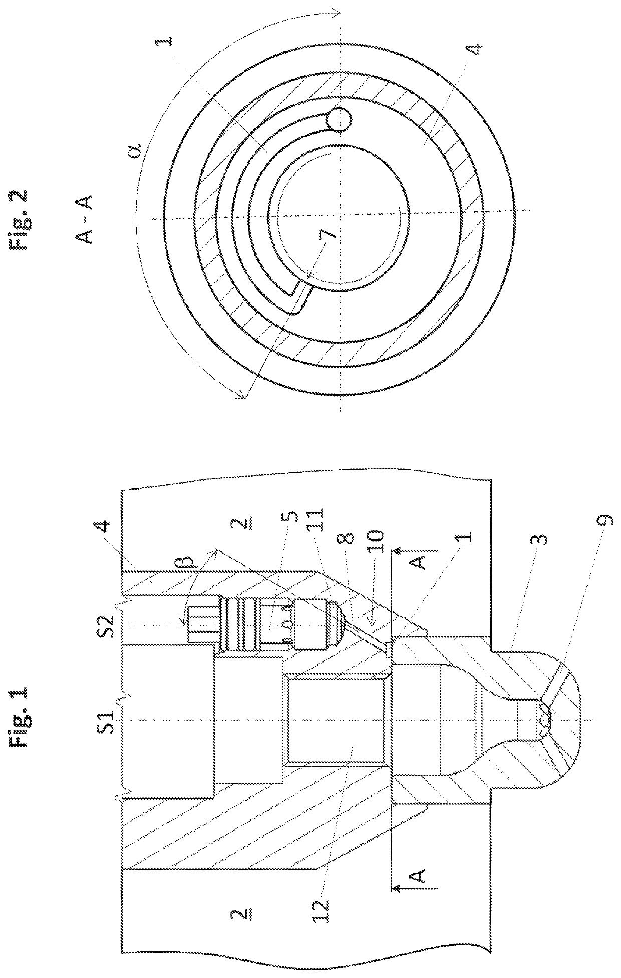
[0039]FIGS. 1 and 2 show a cylinder head 2 for an internal combustion engine having a prechamber 3. The prechamber gas valve 5 and a spark plug (not shown for reasons of clarity) are fitted in a spark plug sleeve 4. In the installation position, the spark plug sleeve 4 is fitted into the cylinder head 2 of the internal combustion engine (not shown here in its entirety).

[0040]FIG. 1 shows a longitudinal section through the cavity of the cylinder head 2 into which the spark plug sleeve 4 is fitted. The spark plug sleeve 4 includes a shaft which is concentric around the axis of symmetry S1 and comprises cylindrical portions for receiving a spark plug and it has a bore with the axis of symmetry S2 for receiving a prechamber gas valve 5.

[0041]A flow transfer passage 10 leads from the prechamber gas valve 5 to the prechamber 3. The prechamber 3 comprises the actual prechamber space 6, that is to say a hollow space in which the ignition of mixture takes place and the flow transfer bores 9,...

second embodiment

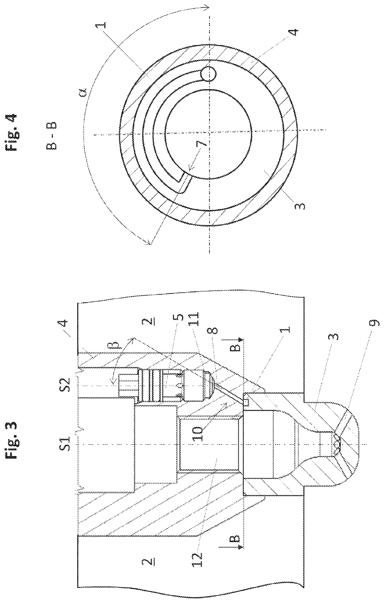
[0045]FIGS. 3 and 4 show a cylinder head 2 for an internal combustion engine. Unlike FIGS. 1 and 2, in the embodiment of FIGS. 3 and 4 the second portion 1 of the flow transfer passage 10 is provided in the prechamber 3. That is particularly clear from FIG. 3. FIG. 4 in turn shows the section B-B indicated in FIG. 3 through the separation plane between the prechamber 3 and the spark plug sleeve 4.

[0046]In FIGS. 3 and 4, the second portion 1 of the flow transfer passage 10 extends in an angular range a around a part of a periphery of the prechamber 3, wherein the second portion 1 (apart from that opening 7 with which it opens into the prechamber space 6) has an uninterrupted peripheral surface. In this embodiment, the second portion 1 of the flow transfer passage 10 is provided by a milled groove in the prechamber 3, that is closed by the adjoining wall of the spark plug sleeve 4 and forms a passage (second portion 1 of the flow transfer passage 10).

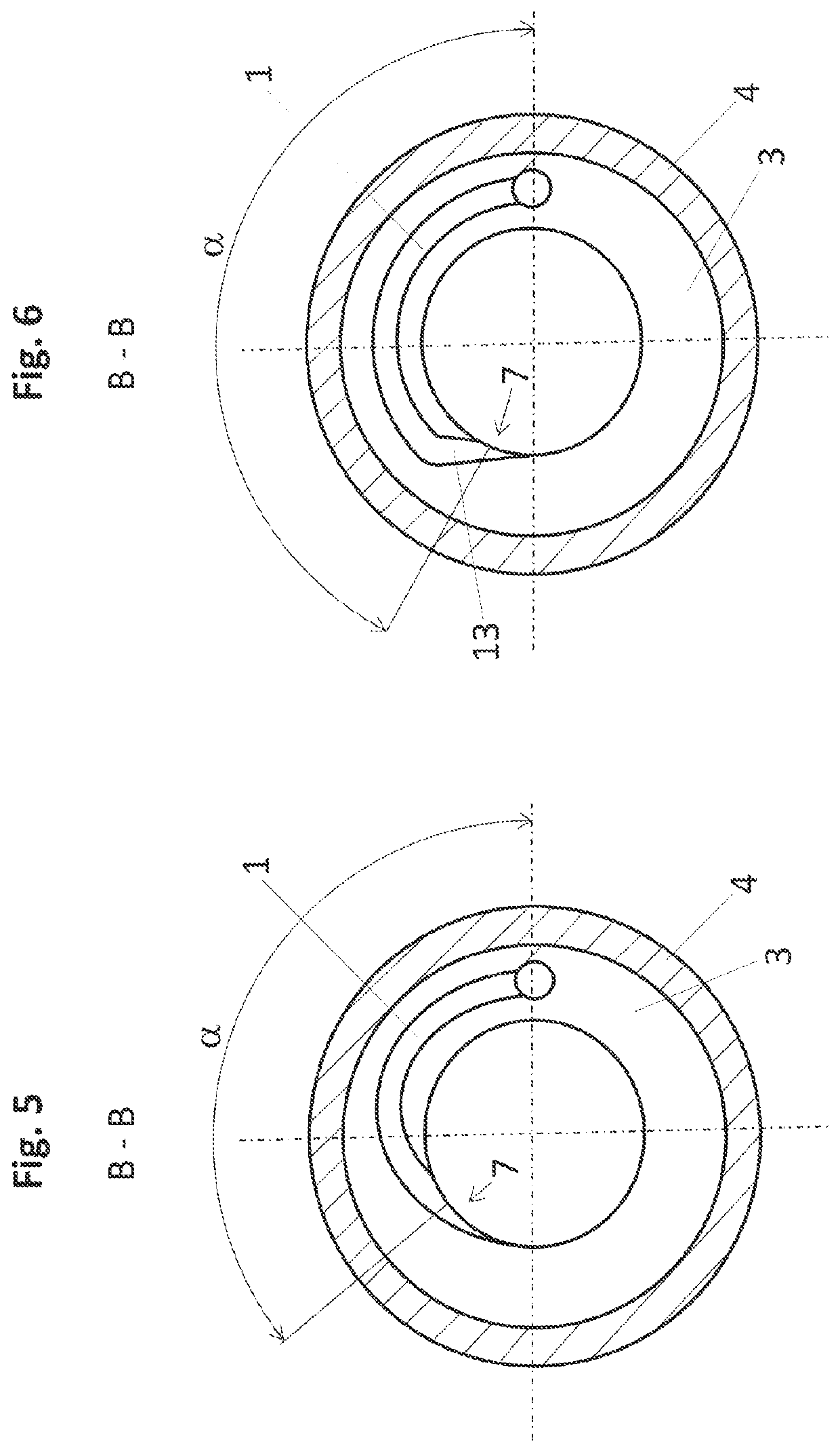
[0047]FIGS. 5 and 6 show alternati...


PUM


Abstract

A cylinder head for an internal combustion engine comprising a prechamber (3), wherein a prechamber gas valve (5) is fitted into a cavity in the cylinder head (2) and the prechamber gas valve (5) is connected to the prechamber (3) by way of a flow transfer passage (10), wherein the flow transfer passage (10) has a first portion (8) adjoining the prechamber gas valve (5) and a second portion (1) into which the first portion (8) opens, wherein the second portion (1) extends at least around a part of a periphery of the prechamber (3), wherein the second portion (1) has an uninterrupted peripheral surface apart from that opening (7) with which it passes into the prechamber (3).

Description

CROSS-REFERENCE TO RELATED APPLICATION[0001]This application is a National Stage entry from, and claims benefit of, PCT Application No. PCT / AT2018 / 060315, filed on Dec. 21, 2018; entitled “CYLINDER HEAD FOR AN INTERNAL COMBUSTION ENGINE”, which is herein incorporated by reference in its entirety.BACKGROUND[0002]The present invention concerns a cylinder head and an internal combustion engine having such a cylinder head.[0003]As from a certain diameter of the cylinder bore (about 150 mm), (gas) internal combustion engines are equipped with a prechamber for ignition boosting. An ignition source—usually an ignition spark plug—which projects into the prechamber ignites the mixture which is present therein and which in the case of a flashed prechamber is relatively rich, whereby ignition flares pass from the prechamber into a main combustion chamber and ignite the mixture there.[0004]There are various concepts in regard to the supply of fuel to the prechamber. In the case of an unflashed ...

Claims


Application Information

Patent Timeline
Patent Type & Authority Applications(United States)
IPC IPC(8): F02B19/18F02F1/24F02B19/12
CPCF02B19/18F02B19/12F02F1/242F02B19/1014F02B19/108F02B19/16F02M21/0281Y02T10/30Y02T10/12
Inventor GROTZ, MATTHIASSCHAUMBERGER, HERBERTSPYRA, NIKOLAUSFANKHAUSER, THOMASBEC, ISABELLE
Owner GE JENBACHER
Why Eureka
Try Eureka