Rapid testing device for wastewater analysis

a technology of wastewater analysis and testing device, which is applied in the direction of chemical methods analysis, laboratory glassware, instruments, etc., can solve the problems of increasing the cost and complexity of monitoring environmental conditions, slow and costly process of collecting and transmitting samples to laboratories for analysis, etc., and achieves rapid and simple method, inexpensive chemical compound testing, and the effect of fast determination

Active Publication Date: 2022-03-03
IBM CORP
View PDF0 Cites 2 Cited by
  • Summary
  • Abstract
  • Description
  • Claims
  • Application Information

AI Technical Summary

Benefits of technology

[0004]According to various embodiments, a rapid test device and a method of manufacture are provided herein that provide for the inexpensive testing of c

Problems solved by technology

However, the collecting and transmitting of samples to laboratories for analysis to monitor environmental conditions is a slow and costly process.
There may also be inherent

Method used


Image

  • Rapid testing device for wastewater analysis
  • Rapid testing device for wastewater analysis
  • Rapid testing device for wastewater analysis

Examples


example architecture

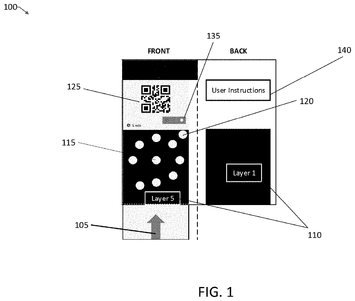
[0033]FIG. 1 illustrates an overview of a rapid testing device 100, consistent with an illustrative embodiment. It is to be understood that the rapid testing device shown is provided for illustrative purposes, and the appended claims are not limited to the illustration shown and described. To facilitate the understanding of the description, both the front and back of the cover elements of the rapid testing device 100 are shown. The paper micropad may be covered by the front cover only, or can be housed within the front and the back covers.

[0034]The rapid testing device 100 includes a sample absorption element 105. In the illustrative embodiment, the sample absorption element 105 extends from the rapid testing device to facilitate dipping a least a portion of the sample absorption element into an input sample.

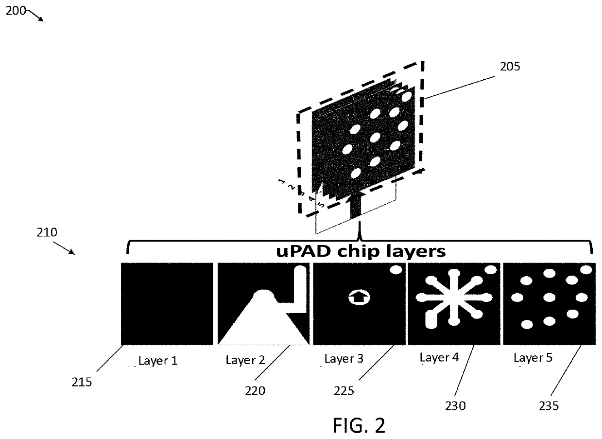
[0035]The sample absorption element 105 is part of the micropad chip (see FIG. 2) used in the rapid testing device 100. In this illustrative embodiment, the micropad chip includ...

example processes

[0052]With the foregoing overview of the example architecture, it may be helpful now to consider a high-level discussion of an example process. To that end, FIG. 7 is a flowchart 700 of a manufacturing process of a rapid testing device shown in FIGS. 1, 2 and 3. More specifically, FIG. 7 is a flowchart illustrating a method of manufacturing a rapid test device, consistent with an illustrative embodiment.

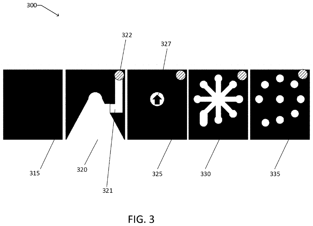
[0053]At operation 710, a micropad is provided with a plurality of paper layers with a hydrophobic material configured to provide hydrophilic channels. The micropad is configured to contain a plurality of reacting element layers with a plurality of colorimetric reagents embedded in the fibers of the paper channel and in fluid communication with the sample distribution element. The construction of channels on the paper-based layers permits multi-parameter rapid testing of multiple chemical compounds from a single test device.

[0054]At operation 720, a sample absorption element layer is...


PUM


Abstract

A rapid test device includes a micropad chip configured for a multi-parameter chemical testing of an input sample. A plurality of paper layers of the micropad chip are in fluid communication, including a sample absorption element, a filtering element configured to filter the input sample, and a sample distribution element configured to distribute the input sample received from the filtering element to a remainder of the plurality of paper layers. One or more reacting elements associated with the multi-parameter chemical testing of the input sample have one or more colorimetric reagents in fluid communication with the sample distribution element. A colorimetric result displaying element in fluid communication with the one or more reacting elements is configured to display a colorimetric result of the testing of the input sample with the at least one reacting element for a respective chemical test of the multi-parameter chemical testing.

Description

BACKGROUNDTechnical Field[0001]The present disclosure generally relates to testing devices for monitoring environmental conditions, and more particularly, to rapid testing devices.Description of the Related Art[0002]Today, there are increased efforts being made to monitor environmental conditions in a variety of agricultural and manufacturing operations. As the population increases worldwide, to ensure such operations do not adversely impact ecosystems is a salient element of providing for the health and safety of future generations.[0003]However, the collecting and transmitting of samples to laboratories for analysis to monitor environmental conditions is a slow and costly process. For example, conventional monitoring often relies on titrimetric, electrometric, turbimetric, nephelometric, or colorimetric protocols carried out in a laboratory. The use of portable kits is less costly, but involves careful preparation steps and thorough cleaning of instrumentation after each use. Ther...

Claims


Application Information

Patent Timeline
IPC IPC(8): B01L3/00G01N33/18G01N21/25G01N21/78G06T7/90G06K19/06
CPCB01L3/502715B01L2200/12G01N21/251G01N21/78B01L3/502707G06T7/90G06K19/06037B01L2200/10B01L2300/069B01L2300/0681B01L2300/0864B01L2300/025B01L2300/161B01L2300/021G01N33/18G01N21/80G01N33/1826B01L3/5023B01L2300/0816B01L2300/0803B01L2300/126G01N31/227
Inventor FERREIRA DA SILVA, ADEMIRMARÇAL, DANIEL VITOR LOPES MARCONDESTIRAPU AZPIROZ, JAIONEESTEVES FERREIRA, MATHEUSSTEINER, MATHIAS B.OHTA, RICARDO LUIS
Owner IBM CORP
Why Eureka
Try Eureka