Work machine and method for controlling work machine

Pending Publication Date: 2022-03-03
KOMATSU LTD
View PDF0 Cites 0 Cited by
  • Summary
  • Abstract
  • Description
  • Claims
  • Application Information

AI Technical Summary

Benefits of technology

[0011]In the present disclosure, the fuel consumption can be improved by controlling the transmission in the second mode. In addition, the controller weakens the limit of the target tractive force and determines the target tractive force when the acceleration of the machine during the second mode is less than

Problems solved by technology

However, on flat ground or a road with a low gradient, the vehicle speed or the acceleration of the work machine is decreased.
However, even if the output command of the engine is increased, the actual output of the engine does not increase immediately.
As a result, it is difficult to quickly suppress

Method used


Image

  • Work machine and method for controlling work machine
  • Work machine and method for controlling work machine
  • Work machine and method for controlling work machine

Examples


Example

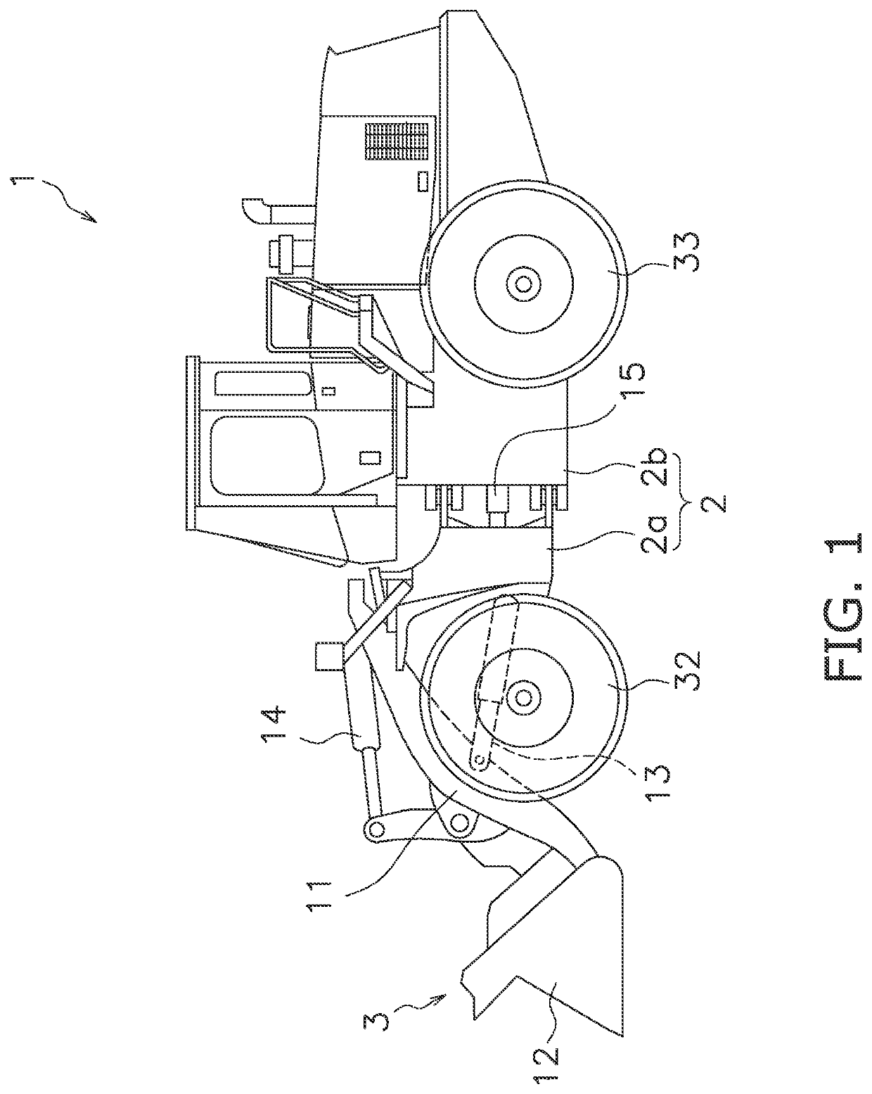
[0022]An embodiment of the present invention will be explained in detail with reference to the figures. FIG. 1 is a side view of a work machine 1 according to an embodiment of the present invention. As illustrated in FIG. 1, the work machine 1 includes a vehicle body 2 and a work implement 3.

[0023]The vehicle body 2 includes a front vehicle body 2a and a rear vehicle body 2b. The rear vehicle body 2b is connected so as to be able to turn to the left and right with respect to the front vehicle body 2a. The front vehicle body 2a and the rear vehicle body 2b are coupled by a hydraulic cylinder 15. The hydraulic cylinder 15 extends and contracts to turn the front vehicle body 2a to the left and right with respect to the rear vehicle body 2b.

[0024]The work implement 3 is used for work such as excavation. The work implement 3 is attached to the front vehicle body 2a. The work implement 3 includes a boom 11, a bucket 12, and hydraulic cylinders 13 and 14. The hydraulic cylinders 13 and 14...


PUM


Abstract

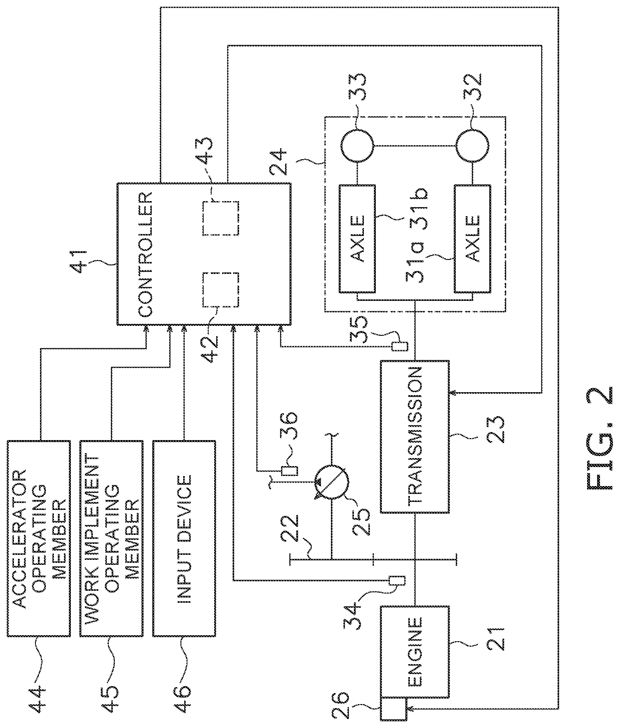
A work machine includes an engine, a transmission connected to the engine to change a transmission gear ratio continuously, a travel device connected to the transmission to cause the work machine to travel, a sensor arranged and configured to detect an acceleration of the work machine, and a controller. The controller selectively execute a first mode and a second mode that limits a target tractive force of the machine in comparison to the first mode. The controller weakens limitation of the target tractive force and determines the target tractive force when the acceleration of the machine in the second mode is less than a predetermined acceleration threshold. The controller determines a target transmission gear ratio in accordance with the target tractive force. The controller controls the transmission based on the target transmission gear ratio.

Description

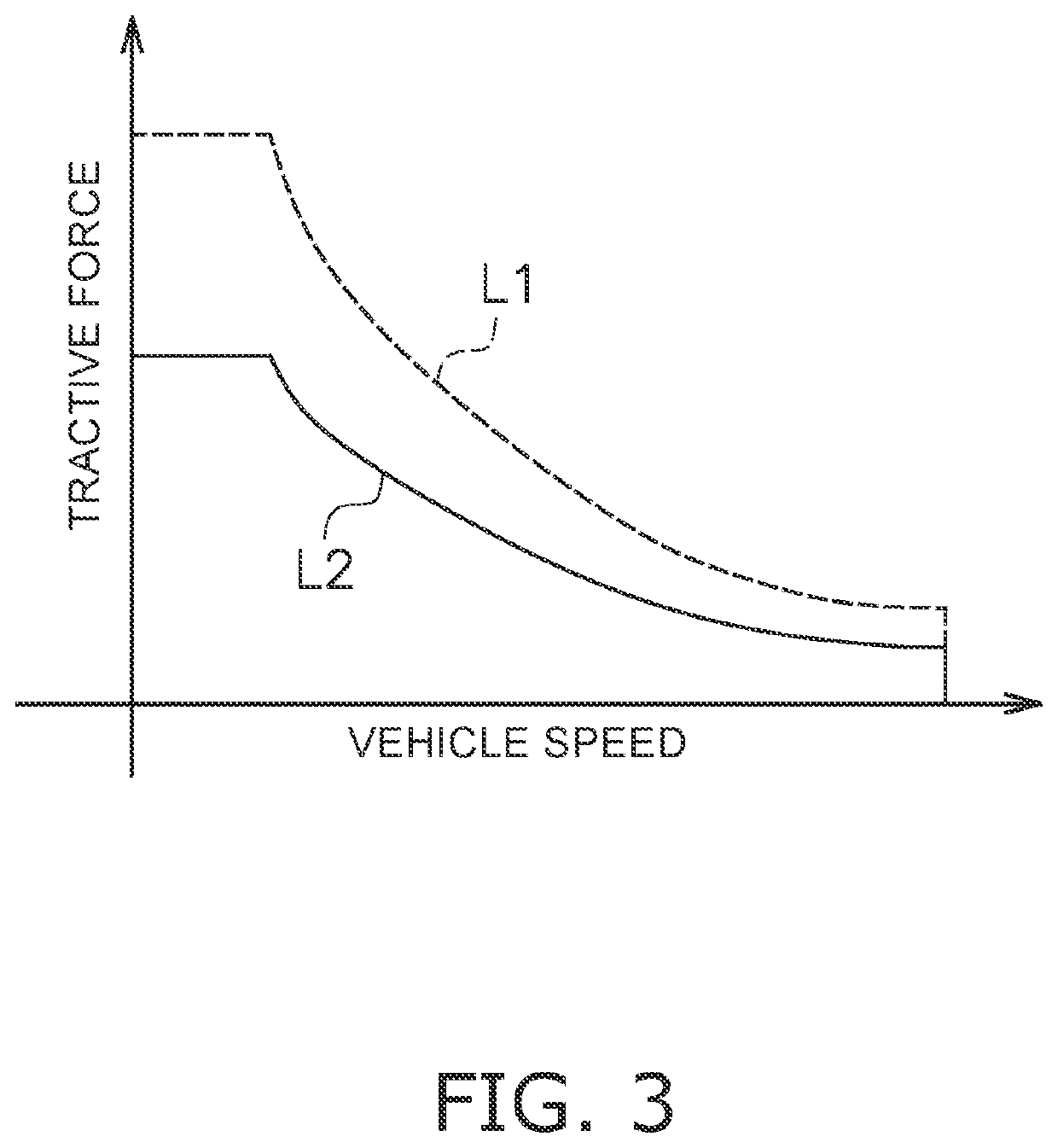
[0001]This application is a U.S. National stage application of International Application No. PCT / JP2020 / 009839, filed on Mar. 6, 2020. This U.S. National stage application claims priority under 35 U.S.C. § 119(a) to Japanese Patent Application No. 2019-062993, filed in Japan on Mar. 28, 2019, the entire contents of which are hereby incorporated herein by reference.BACKGROUNDField of the Invention[0002]The present disclosure relates to a work machine and a method for controlling a work machine.Background Information[0003]As described in WO 2005 / 024208 A1, a high-output mode and a low-output mode are set as control modes for the engine in a work machine. In the low-output mode, the maximum tractive force for each vehicle speed is reduced in comparison to the high-output mode. The switching between the low-output mode and the high-output mode is performed automatically in response to a load applied to the work machine. For example, the high-output mode is selected when the work machine...

Claims


Application Information

Patent Timeline
IPC IPC(8): B60W30/188F16H59/48F16H59/70F16H59/44F16H61/66F16H59/18F02D41/02B60W10/06B60W10/101E02F9/20E02F9/22
CPCB60W30/188E02F9/0841F16H59/70F16H59/44F16H61/66F16H59/18F02D41/0215B60W10/06B60W10/101E02F9/202E02F9/2253B60W2520/105B60W2540/10B60W2710/1005B60W2710/06F16H59/48B60W10/04B60W10/103E02F9/2079F16H2061/0015F16H2061/0227F16H2061/0234F16H2061/0237F16H2061/0216F16H63/50
Inventor TAKENAKA, YUITA
Owner KOMATSU LTD
Why Eureka
Try Eureka