
Construction vehicle with waste heat recovery

Inactive Publication Date: 2014-02-06
BOMAG
View PDF6 Cites 3 Cited by
  • Summary
  • Abstract
  • Description
  • Claims
  • Application Information

AI Technical Summary

Benefits of technology

This patent is about a construction vehicle that has a special converter to convert the heat energy from the engine into mechanical energy. This energy can then be used to power the vehicle and its tools. This improves efficiency and reduces fuel consumption. The design is specifically for construction machines that are always running at high loads, like landfill compactors or road milling machines. The energy converter is integrated into the vehicle's powertrain, so it can be easily connected to the engine. A supplementary transmission can be used to adapt the speed of the converter to the engine's speed. The pump of the converter can also be integrated into the powertrain, eliminating the need for a separate pump. This simplifies the construction vehicle design and reduces its size.

Problems solved by technology

For economic as well as environmental reasons, this release of unused energy in the form of waste heat into the environment is not ideal.
Furthermore, the requirements regarding CO2 emissions and the fuel consumption of construction vehicles are becoming increasingly stricter.

Method used


Image

  • Construction vehicle with waste heat recovery
  • Construction vehicle with waste heat recovery
  • Construction vehicle with waste heat recovery

Examples


Embodiment Construction

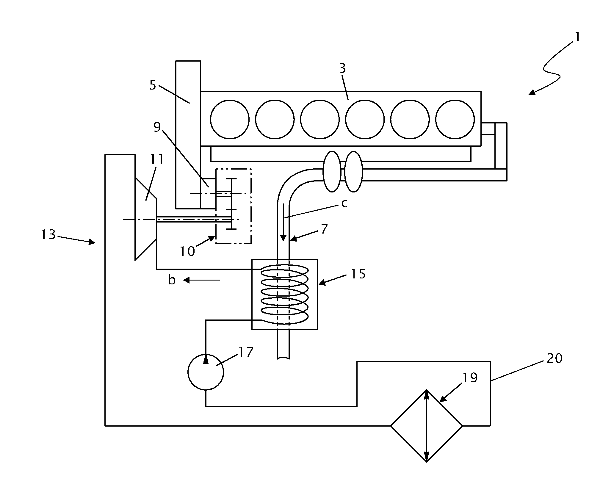
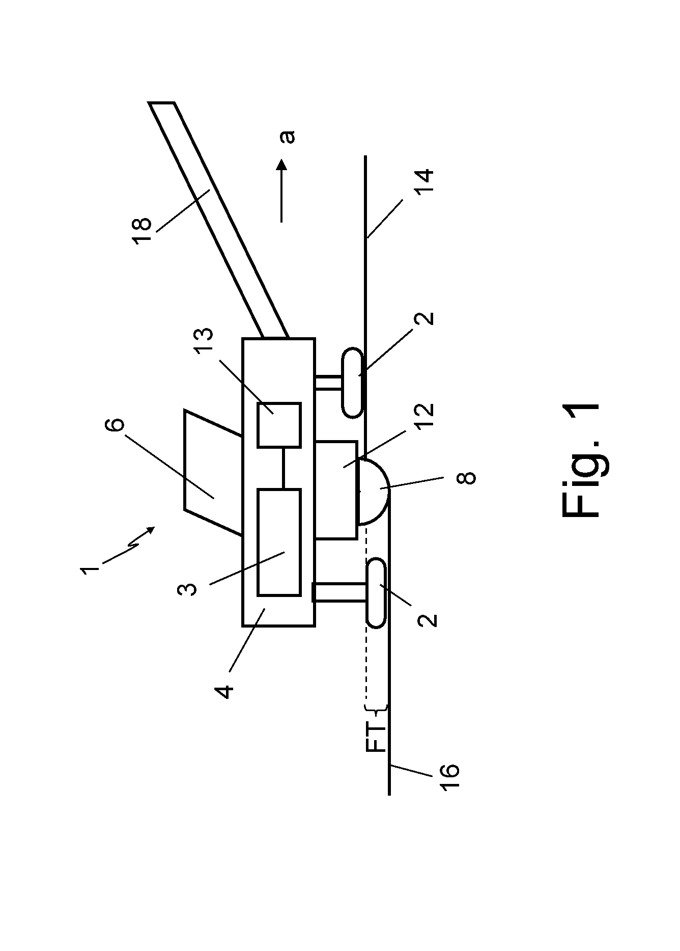
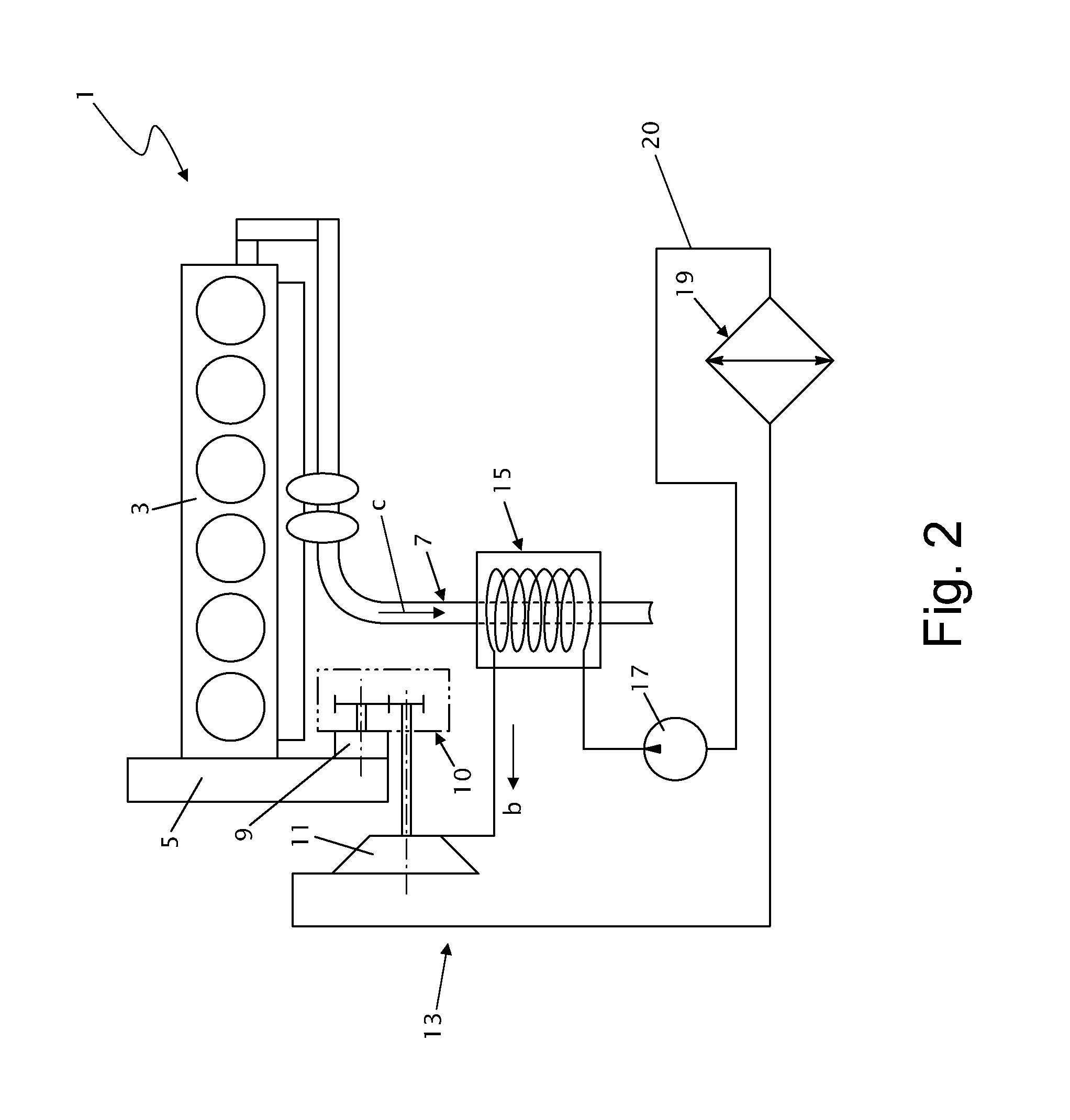
[0031]FIG. 1 illustrates the basic construction of an exemplary construction vehicle 1 for ground processing, in this particular case a road milling machine. The construction vehicle 1 in FIG. 1 is configured for milling off an upper layer of the road surface to a milling depth FT. Essential components of the construction vehicle 1 are a machine frame 4, a chassis with a total of four caterpillar tracks 2 mounted on lifting columns on the machine frame 4, the lifting columns being vertically adjustable, an operator station 6 and a working implement, which in this specific case is a milling drum 8 mounted in a drum housing 12. The milling depth FT can be varied by vertically adjusting the lifting columns so that, for example, the distance of the underside of the vehicle down to the road surface is vertically variable. The milling drum 8 is disposed in the horizontal plane with its axis of rotation R perpendicular to the machine direction “a” of the construction vehicle 1. In the work...


PUM


Abstract

The present invention relates to a construction vehicle comprising a main drive for driving work equipment of the construction vehicle, which main drive comprises at least one internal combustion engine, wherein the construction vehicle comprises an energy converter, which is adapted to convert off gas heat energy from the internal combustion engine to mechanical kinetic energy.

Description

CROSS-REFERENCE TO RELATED APPLICATIONS[0001]The present application claims priority under 35 U.S.C. §119 of German Patent Application No. 10 2012 015 267.1, filed Jul. 31, 2012, the disclosure of which is hereby incorporated herein by reference in its entirety.FIELD OF THE INVENTION[0002]The present invention relates to a construction vehicle, in particular, a landfill compactor (landfill construction), also known as refuse compactor, or a road milling machine (road construction), having a main drive comprising at least one internal combustion engine by means of which at least part of the operating power needed to run the construction vehicle is provided.BACKGROUND OF THE INVENTION[0003]Such construction vehicles typically always comprise an engine, in particular, an internal combustion engine, for traction and also for driving working implements such as milling drums, conveyors, hydraulic pumps, compactors, etc., mounted on the construction vehicle. The internal combustion engine ...

Claims


Application Information

Patent Timeline
IPC IPC(8): F02B27/00
CPCF02B27/00F01N5/02Y02T10/12
Inventor LAUX, ROBERTREUTER, MARCO
Owner BOMAG
Learn More