Control apparatus for vehicle, vehicle and method of controlling vehicle
- Summary
- Abstract
- Description
- Claims
- Application Information
AI Technical Summary
Benefits of technology
Problems solved by technology
Method used
Image
Examples
first embodiment
A. First Embodiment
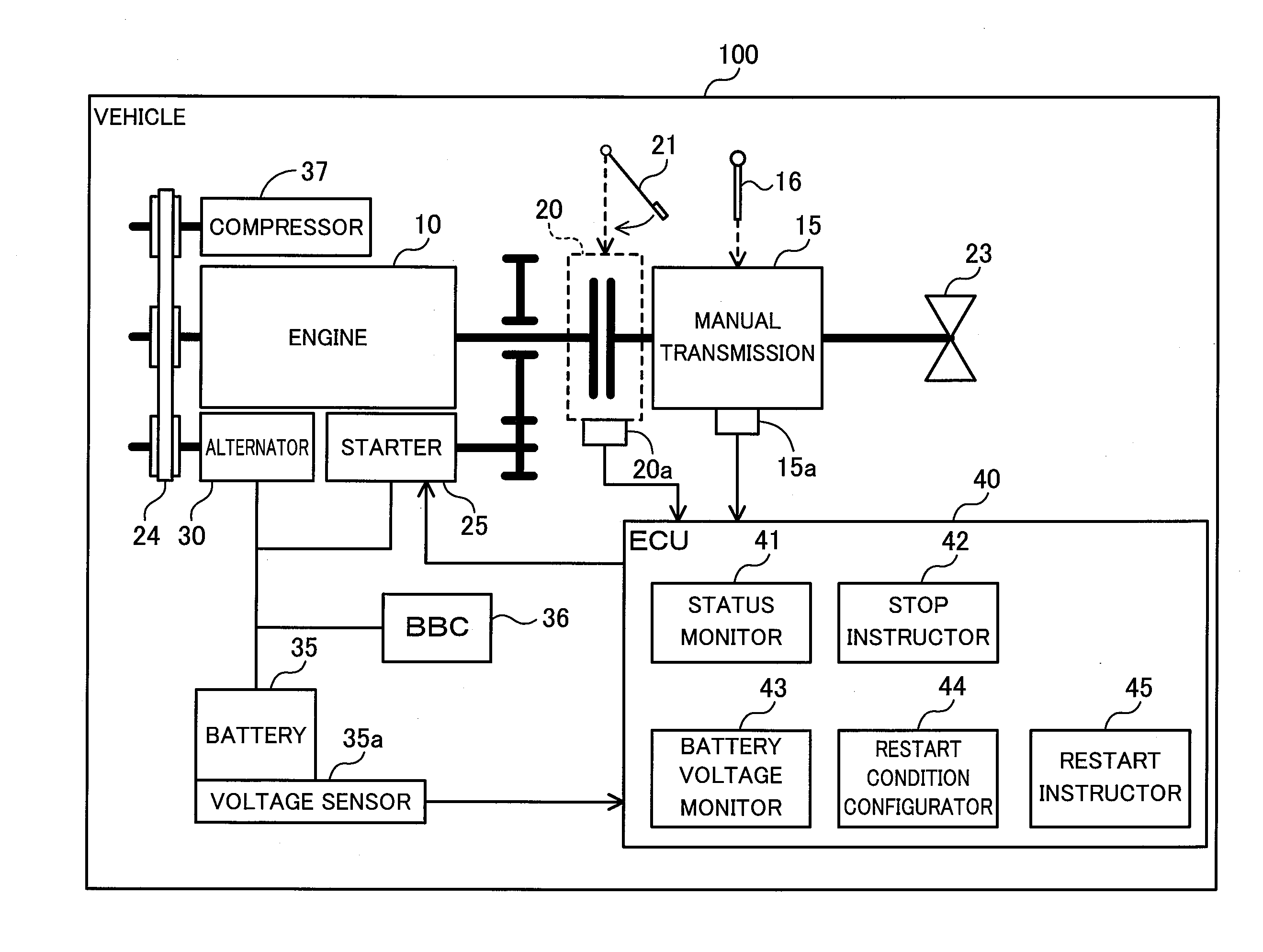
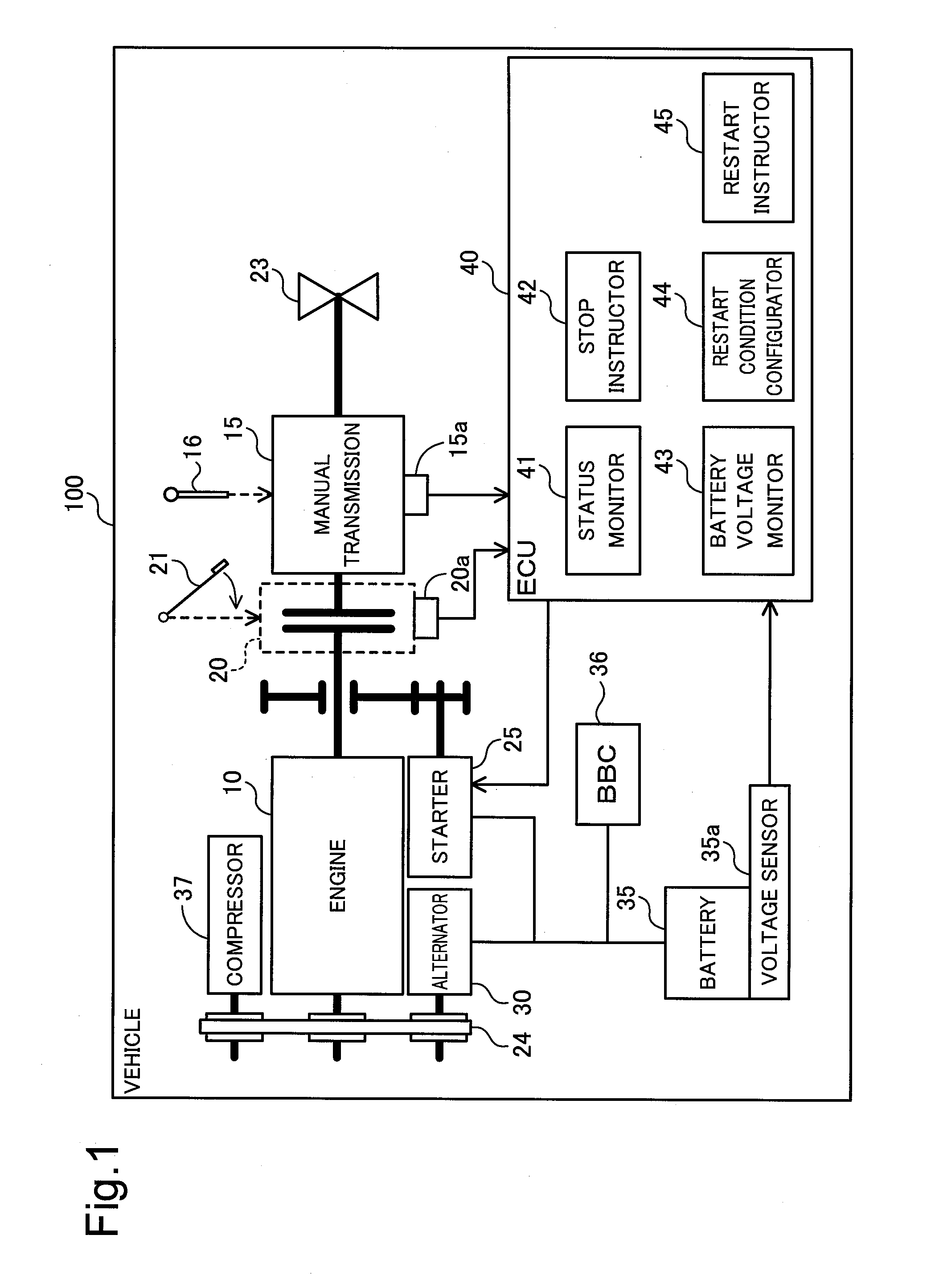
[0043]FIG. 1 is a diagram illustrating the configuration of a vehicle 100 according to one embodiment of the invention. The vehicle 100 is an MT vehicle having the function of idle reduction to stop an engine when the vehicle is stopped and to restart the engine at a specified timing. The vehicle 100 includes an engine 10, a manual transmission 15, a clutch 20, a differential gear 23, a drive mechanism 24, a starter 25, an alternator 30, a battery 35, a back-up boost converter (BBC) 36, a compressor 37 and an electrical control unit (ECU) 40.
[0044]Additionally, as various sensors, the manual transmission 15 is provided with a gearshift sensor 15a; the clutch 20 is provided with a clutch sensor 20a; and the battery 35 is provided with a voltage sensor 35a. In the specification hereof, peripheral equipment provided other than the engine body to operate with the electric power of the battery 35, for example, the starter 25, an ignition plug (not shown) and an air con...
second embodiment
B. Second Embodiment
[0067]FIG. 4 is a diagram illustrating the configuration of a vehicle 100b according to a second embodiment. The second embodiment differs in only the following points from the first embodiment shown in FIG. 1 but otherwise has the same configuration as that of the first embodiment:
[0068]providing a temperature sensor 35b to detect the temperature of the battery 35, in place of the voltage sensor 35a;
[0069]providing a battery temperature monitor 43b to monitor the temperature of the battery 35, in place of the battery voltage monitor 43; and
[0070]the restart condition configurator 44b sets the restart condition of the engine 10 based on the temperature of the battery 35, instead of based on the voltage of the battery 35.
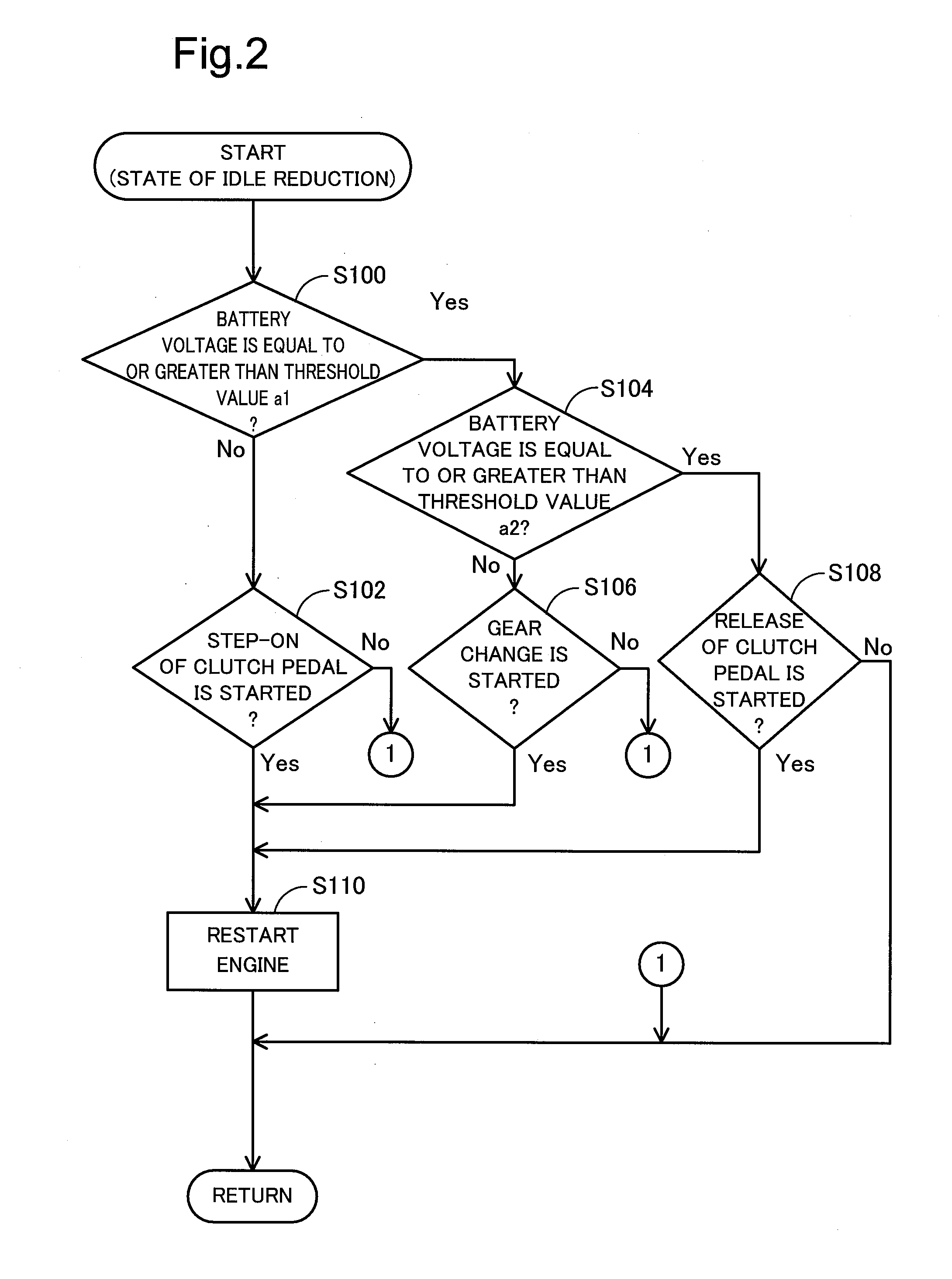
[0071]FIG. 5 is a flowchart showing a processing flow to restart the engine 10 after idle reduction in the vehicle 100b of the second embodiment. This processing flow differs from the first embodiment shown in FIG. 2 in that the restart condition...
modification 2
C2. Modification 2
[0077]In the above embodiments, the restart condition configurator sets the restart condition of the engine 10, based on either one of the voltage and the temperature of the battery 35. The restart condition configurator may, however, set the restart condition of the engine 10, based on both the voltage and the temperature of the battery 35. In the latter case, the restart condition configurator may use a table having the voltage and the temperature of the battery 35 as two inputs and the restart condition of the engine 10 as one output.
PUM
 Abstract
Description
Claims
Application Information
 - R&D
- Intellectual Property
- Life Sciences
- Materials
- Tech Scout
- Unparalleled Data Quality
- Higher Quality Content
- 60% Fewer Hallucinations
Browse by: Latest US Patents, China's latest patents, Technical Efficacy Thesaurus, Application Domain, Technology Topic, Popular Technical Reports.
© 2025 PatSnap. All rights reserved.Legal|Privacy policy|Modern Slavery Act Transparency Statement|Sitemap|About US| Contact US: help@patsnap.com


