Split iron frame door structure

a door structure and iron frame technology, applied in the direction of walls, constructions, building components, etc., can solve the problems of high transportation cost, inconvenient logistics transportation, heavy iron frame doors, etc., and achieve the reduction of overall weight of iron frame doors, packaging costs and transportation costs, and the effect of reducing the overall weight of the iron frame doors

Active Publication Date: 2022-03-03
NINGBO TENGYU METAL PROD
View PDF0 Cites 0 Cited by
  • Summary
  • Abstract
  • Description
  • Claims
  • Application Information

AI Technical Summary

Benefits of technology

[0011]Compared with the prior art, the split iron frame door structure in the disclosure has the advantages as follows. The split iron frame door structure adopts the split design, and the top split frame, the middle split frame and the bottom split frame thereof can be individually packaged, and transported to an installation site and then spliced and installed, so that the packaging cost and the transportation cost can be reduced. The frames of the top split frame, the middle split frame and the bottom split frame of the split iron frame door structure are made of thin-wall square tubes and the flat iron, so that the thickness of the frames is reduced, the overall weight of the iron frame door is reduced, the appearance of the iron frame door is more concise, and the light transmittance of the iron frame door is improved.

Problems solved by technology

So, the packaged iron frame door is large in size, the logistics transportation is inconvenient, and the transportation cost is high.
In addition, a thickness of the material for the frame of the iron frame door is thick, so that the iron frame door is heavy.
And meanwhile, the area of the glass is reduced to a certain extent because the thickness of the material of the frame is thick, thus the iron frame door has the problem that the light transmittance thereof is low.
The technical problem to be solved by the disclosure is to provide a split iron frame door structure in view of the defects in the prior art.

Method used


Image

  • Split iron frame door structure
  • Split iron frame door structure
  • Split iron frame door structure

Examples


Embodiment Construction

[0022]The description of the disclosure is further described in conjunction with the following accompany drawings and embodiments.

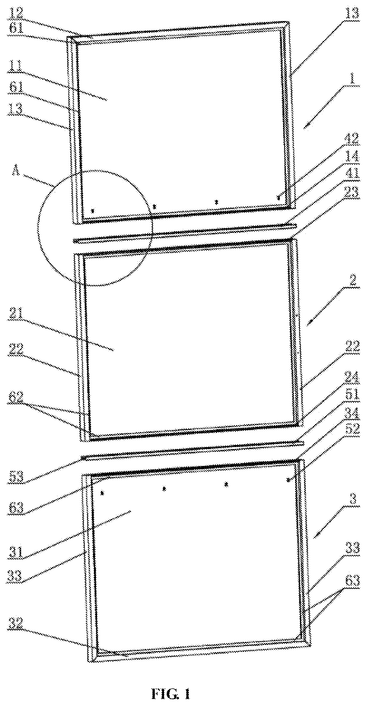
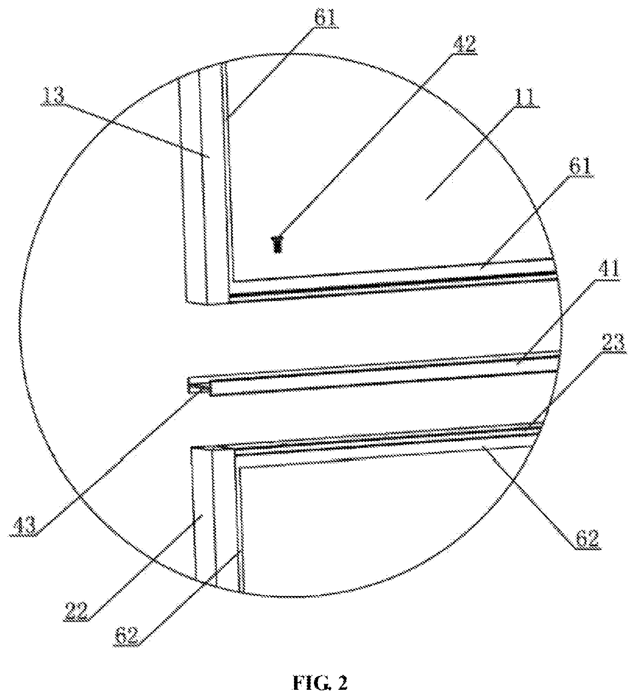
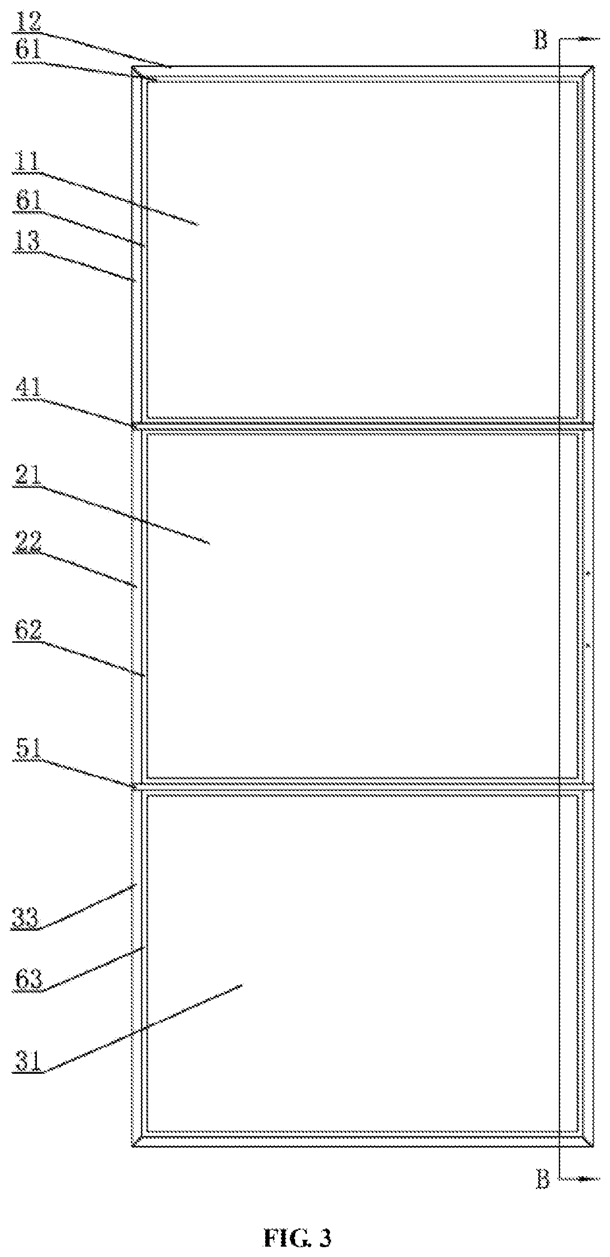
[0023]A split iron frame door structure in the first example, as shown in figures, includes a top split frame 1, a middle split frame 2 and a bottom split frame 3 which are detachably connected in sequence from top to bottom. The top split frame 1 includes two side edge frames 13, top glass 11, and a top edge frame 12 which are connected as a whole. The middle split frame 2 includes two side edge frames 22 and middle glass 21 which are connected as a whole. The bottom split frame 3 includes two side edge frames 33, bottom glass 31, and a bottom edge frame 32 which are connected as a whole. The top edge frame 12 and the two side edge frames 13 of the top split frame 1, the two side edge frames 22 of the middle split frame 2, and the bottom edge frame 32 and the two side edge frames 33 of the bottom split frame 3 are thin-wall square tube frames. A transver...


PUM


Abstract

There provides a split iron frame door structure including top, middle and bottom split frames. A top edge frame and two side edge frames of the top split frame, two side edge frames of the middle split frame, and a bottom edge frame and two side edge frames of the bottom split frame are thin-wall square tubes. A transversely-arranged first flat-iron edge frame is fixed to the bottom of the top split frame. Transversely-arranged second and third flat-iron edge frames are fixed to the top and the bottom of the middle split frame, respectively. A transversely-arranged fourth flat-iron edge frame is fixed to the top of the bottom split frame. The first and second flat-iron edge frames are detachably connected through a first I-shaped section material and first connecting screws. The third and fourth flat-iron edge frames are detachably connected through a second I-shaped section material and second connecting screws. The iron frame door structure adopts a split design, and is low in packaging cost and transportation cost, light in overall weight, concise in appearance and good in light transmittance.

Description

TECHNICAL FIELD[0001]The disclosure relates to an iron frame door structure, and specifically relates to a split iron frame door structure.BACKGROUND ART[0002]At present, an iron frame door provided with glass in the market is usually welded and assembled as a whole before leaving a factory, and this iron frame door is packaged wholly when leaving the factory. So, the packaged iron frame door is large in size, the logistics transportation is inconvenient, and the transportation cost is high. In addition, a thickness of the material for the frame of the iron frame door is thick, so that the iron frame door is heavy. And meanwhile, the area of the glass is reduced to a certain extent because the thickness of the material of the frame is thick, thus the iron frame door has the problem that the light transmittance thereof is low.SUMMARY[0003]The technical problem to be solved by the disclosure is to provide a split iron frame door structure in view of the defects in the prior art. The t...

Claims


Application Information

Patent Timeline
Patent Type & Authority Applications(United States)
IPC IPC(8): E06B3/72E06B3/46
CPCE06B3/72E06B3/4636E06B3/7003E06B2003/7011E06B2003/7074E06B3/5892E04B2/7455
Inventor ZHANG, PEIKEJIANG, JUNHUAXU, YECHENWU, ZHEWEIYING, LEI
Owner NINGBO TENGYU METAL PROD
Why Eureka
Try Eureka