Method for improving performance of a sodar system

a technology of sodar system and performance improvement, applied in the field of sodar system, can solve the problems of system prone to doppler error in measurement, excessive resolution, and wind speed height error double what it otherwise is, and achieve the effect of reducing error

Pending Publication Date: 2022-03-03
ELECTRO MAGNETIC MEASUREMENTS PTY LTD
View PDF6 Cites 0 Cited by
  • Summary
  • Abstract
  • Description
  • Claims
  • Application Information

AI Technical Summary

Benefits of technology

[0011]According to an aspect of the present invention, there is provided a method of reducing error in a SODAR system adapted to locate discontinuities in the atmosphere over a range extending away from an acoustic transmitter and receiver, the method comprising the steps of: measuring wind to determine either a substantially upwind direction or a substantially downwind direction relative to the transmitter; transmitting one or more forward or reverse acoustic chirps in the substantially upwind or downwind direction; receiving one or more acoustic echoes of the transmitted chirps; and processing the acoustic echoes to provide an indication of the discontinuities in the atmosphere over the range, thereby providing a wind shear profile.

Problems solved by technology

Use of relatively wideband acoustic chirps in SODAR systems (to realize the full advantages of pulse compression) provides many potential advantages over conventional short pulse single frequency systems including increased gain and better resolution but also introduces several problems including problems associated with systematic Doppler errors in measurements used to obtain the wind speed and direction, which may be introduced into the wind speed and direction measurements.
However, such systems are prone to Doppler errors in measurements used to obtain the wind speed and direction.
In this context systematic Doppler errors relate to wind speed height (range) errors where the wind speed measured at a given height is displaced to a greater or lesser height on opposite beams (North and South or East and West for instance), resulting in excessive resolution and wind speed height errors that are double what they otherwise could be if such range displacements could be arranged to be in the same direction.

Method used


Image

  • Method for improving performance of a sodar system
  • Method for improving performance of a sodar system
  • Method for improving performance of a sodar system

Examples


Embodiment Construction

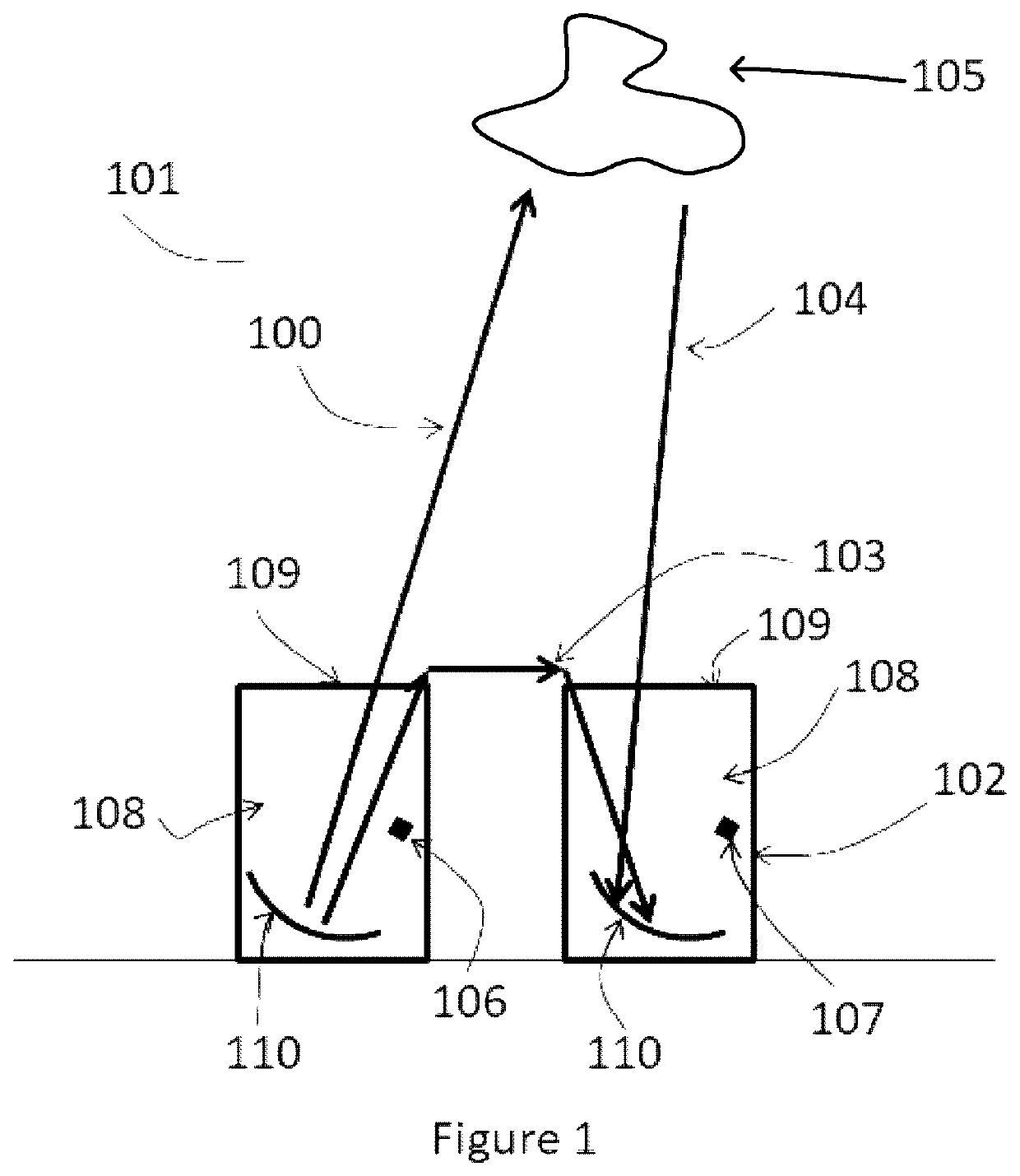
[0052]FIG. 1 shows a pulse compression SODAR system 101 that uses acoustic chirp signals suitable for locating discontinuities in the atmosphere.

[0053]Referring to FIG. 1, a chirp signal 100 comprising an audio signal that increases or decreases in frequency over time is generated and amplified before application to a loudspeaker 106 (transmitting acoustic transducer, or transmitter) and reflector system 110 which directs acoustic energy upwards. The acoustic energy is reflected from discontinuities in the atmosphere 105. The reflected signal 104 is received by a microphone (receiving acoustic transducer, or receiver) 107 and parabolic reflector dish 110. The loudspeaker 106 and microphone 107 are each located within its own separate acoustic baffle 108 that is open only at the top 109.

[0054]The loudspeaker 106 and acoustic baffle 108 are preferably arranged so that the acoustic output of the loudspeaker 106 is directed upwards. The microphone 107 and its acoustic baffle 108 may als...


PUM


Abstract

This invention relates to a method of reducing error in a SODAR system adapted to locate discontinuities in the atmosphere over a range extending away from an acoustic transmitter and receiver, the method comprising the steps of: measuring wind to determine either a substantially upwind direction or a substantially downwind direction relative to the transmitter; transmitting one or more forward or reverse acoustic chirps in the substantially upwind or downwind direction; receiving one or more acoustic echoes of the transmitted chirps; and processing the acoustic echoes to provide an indication of the discontinuities in the atmosphere over the range, thereby providing a wind shear profile.

Description

[0001]This application claims priority from Australian Provisional Patent Application No. 2018904863 filed on 20 Dec. 2018, the contents of which are to be taken as incorporated herein by this reference.TECHNICAL FIELD[0002]The present invention relates to the field of SODAR systems for use in atmospheric sounding and in particular relates to a method and system for correcting Doppler induced wind speed range errors.BACKGROUND OF INVENTION[0003]SODAR systems use pulse compression of acoustic signals (preferably acoustic chirps) that have relatively wide bandwidth (when compared to conventional short pulse SODAR systems) to obtain vertical wind speed and direction as well as large and small scale turbulence.[0004]Use of relatively wideband acoustic chirps in SODAR systems (to realize the full advantages of pulse compression) provides many potential advantages over conventional short pulse single frequency systems including increased gain and better resolution but also introduces seve...

Claims


Application Information

Patent Timeline
Patent Type & Authority Applications(United States)
IPC IPC(8): G01P21/02G01P5/24
CPCG01P21/025G01P5/244G01S15/885G01S15/588G01S15/104G01S15/34G01S15/12G01S15/02G01P13/02G01P5/02G01S7/521G01S15/586G01S15/87G01P5/241G01S15/582
Inventor MARTIN, ANDREW LOUIS
Owner ELECTRO MAGNETIC MEASUREMENTS PTY LTD
Why Eureka
Try Eureka