
High-efficiency llc resonant converter

Active Publication Date: 2022-03-03
CHANNEL WELL TECH
View PDF0 Cites 1 Cited by
  • Summary
  • Abstract
  • Description
  • Claims
  • Application Information

AI Technical Summary

Benefits of technology

The patent is for a device that controls the output voltage of a DC power supplying unit to improve conversion efficiency. It uses a first control unit and a second control unit that work together with an isolation feedback unit to send signals to a switch element of the DC power supplying unit. This results in a modulation of the output voltage and keeps the conversion efficiency of the LLC resonant converter high.

Problems solved by technology

Hence it is a greater challenge for SMPS device to exhibit higher conversion efficiency and large power density with a small device volume.
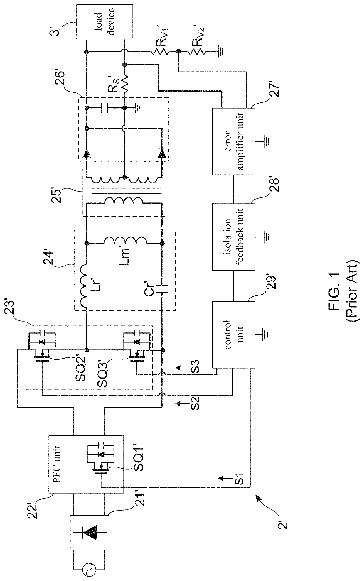
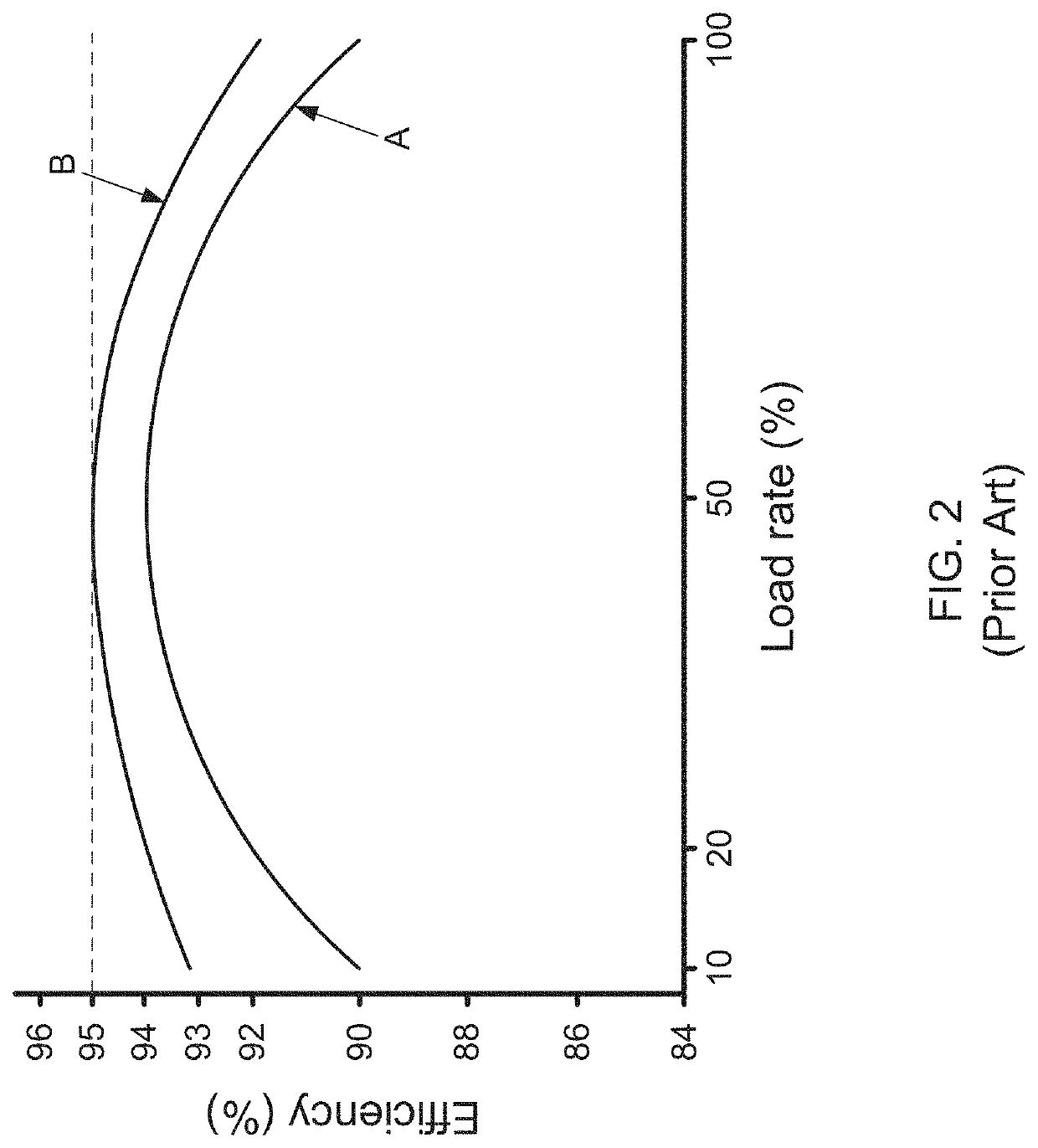
However, in a real case, it is impossible to directly modulate the switching frequency (fS) to be approach the resonant frequency (fr) of the LLC resonant tank during a fast change of the load rate of the LLC resonant converter 2′, thereby resulting in a large reduction of a conversion efficiency of the LLC resonant converter 2′.

Method used


Image

  • High-efficiency llc resonant converter
  • High-efficiency llc resonant converter
  • High-efficiency llc resonant converter

Examples


first embodiment

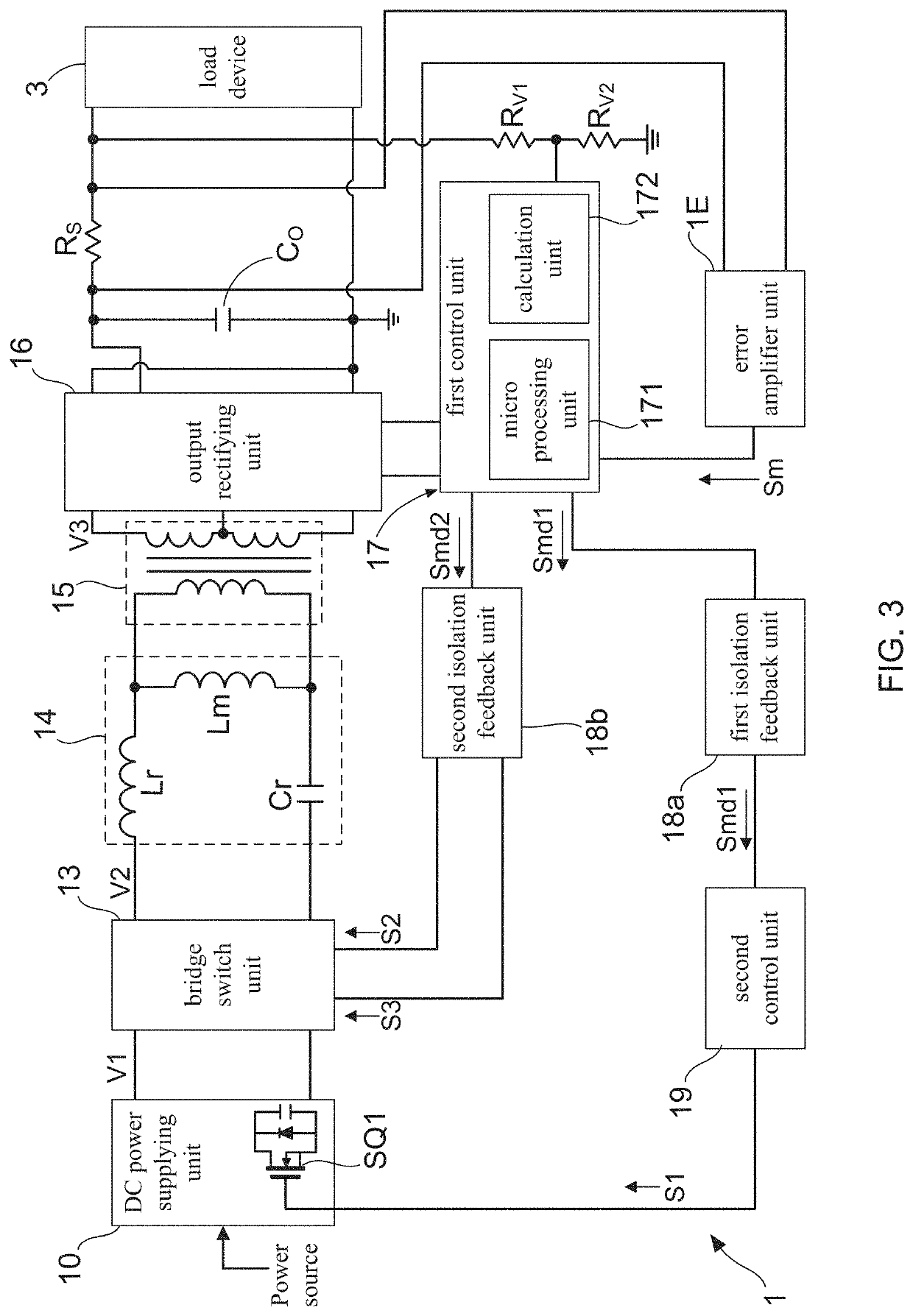
[0084]With reference to FIG. 7, there is shown a block diagram of a high-efficiency LLC resonant converter according to the present invention. As FIG. 7 shows, in second embodiment, the high-efficiency LLC resonant converter 1 comprises: a DC power supplying unit 10, a bridge switch unit 13, a resonant unit 14, a transformer unit 15, an output rectifying unit 16, a detection unit Rs, a first control unit 17, an error amplifier unit 1E, a first isolation feedback unit 18a, and a second control unit 19.

[0085]The DC power supplying unit 10 has at least one first switch element SQ1, and is configured for receiving a power signal, thereby outputting a first voltage signal V1 after applying a power conversion process to the power signal. Moreover, the bridge switch unit 13 is coupled to the DC power supplying unit 10 for receiving the first voltage signal V1, and the resonant unit 14 comprises a resonant inductor Lr and a resonant capacitor Cr, and is coupled to a second voltage signal th...


PUM


Abstract

A high-efficiency LLC resonant converter is disclosed. During a normal operation of the LLC resonant converter, an error amplifier unit generates a modulated voltage signal to a first control unit after receives a data of voltage difference from a detection unit, and then the first control unit calculates an immediate load rate based on the modulated voltage signal. Subsequently, the second control unit receives a first adjustment signal that is outputted by the first control unit, so as to correspondingly generate a switch element controlling signal to a switch element of a DC power supplying unit of the LLC resonant converter, thereby achieving an output voltage modulation of the DC power supplying unit. As such, the LLC resonant converter is controlled to exhibit a conversion efficiency of at least 98% in case of working at any one load state.

Description

BACKGROUND OF THE INVENTION1. Field of the Invention[0001]The present invention relates to the technology field of switching-mode power supply (SMPS), and more particularly to a high-efficiency LLC resonant converter.2. Description of the Prior Art[0002]Switching-mode power supply devices have been widely applied in electronic products and electrical apparatuses. As miniaturization and light weight are the prevailing trend for design of an electronic product, a higher power density is required on SMPS device. Hence it is a greater challenge for SMPS device to exhibit higher conversion efficiency and large power density with a small device volume. Accordingly, LLC resonant converter is developed and proposed. The switching loss of the LLC resonant converter becomes very small because either voltage or current is zero when it is switch on or off Switching at zero-voltage crossing is called zero-voltage switching (ZVS) whereas switching at zero-current crossing is called zero-current s...

Claims


Application Information

Patent Timeline
IPC IPC(8): H02M3/335H02M1/08
CPCH02M3/33592H02M1/4208H02M1/08H02M3/01H02M1/007H02M1/0009Y02B70/10Y02P80/10
Inventor PAN, YI-AN
Owner CHANNEL WELL TECH
Learn More