
Steering column for a steer-by-wire steering system for a motor vehicle

a technology of steering column and steering system, which is applied in the direction of mechanical steering, power steering steering, vehicle components, etc., can solve the problems of impaired steering capability of the vehicle, difficulty for the driver, impaired driving safety, etc., and achieves reduced risk of injury, reduced rigidity, and shorter dimensions

Pending Publication Date: 2022-03-10
THYSSENKRUPP PRESTA AG +1
View PDF0 Cites 2 Cited by
  • Summary
  • Abstract
  • Description
  • Claims
  • Application Information

AI Technical Summary

Benefits of technology

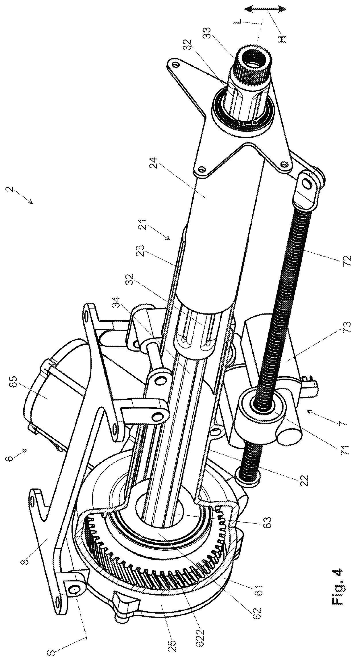
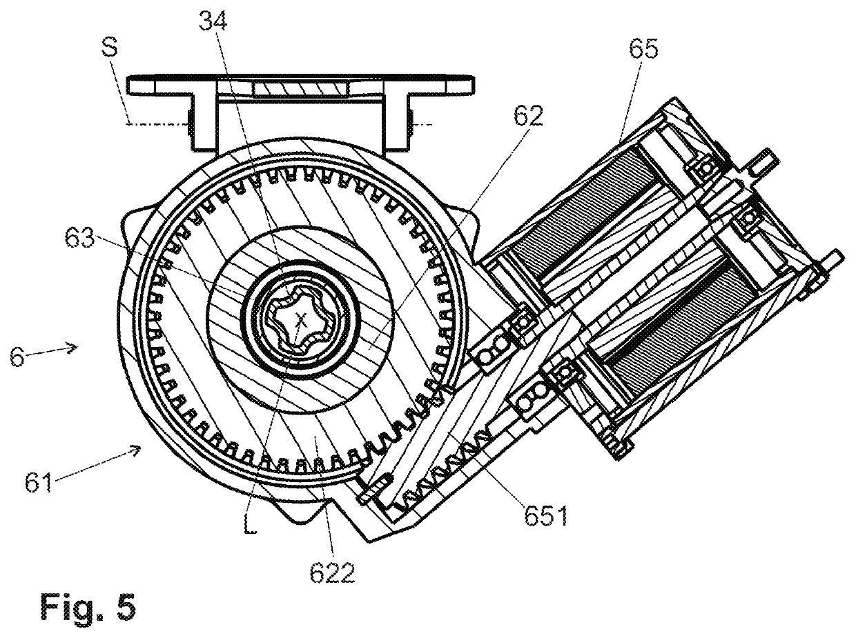
The invention is a steering column for vehicles that has a recess where the outer shaft can retract and extend. This allows for a compact design when the column is fully extended or retracted. In the case of a crash, the steering column can yield and absorb the impact, reducing the risk of injury. The recess also allows for a controlled braking of the vehicle, using energy absorption apparatuses integrated into the steering column. The overall length of the steering column is reduced, making it advantageous for autonomous driving. The recess is open on its side facing the outer shaft, allowing for protection against external influences. The inner casing tube has a smaller diameter than the outer casing tube, making it possible to design the steering column with smaller dimensions in the retracted stowage position. A telescopic adjustment of the casing tubes can be used to achieve a shorter stowage length in the maximum retracted stowage position.

Problems solved by technology

An absence of haptic feedback makes it difficult for the driver, however, to reliably detect current driving situations and to carry out suitable steering maneuvers, as a result of which the vehicle steering capability and therefore the driving safety are impaired.

Method used


Image

  • Steering column for a steer-by-wire steering system for a motor vehicle
  • Steering column for a steer-by-wire steering system for a motor vehicle
  • Steering column for a steer-by-wire steering system for a motor vehicle

Examples


Embodiment Construction

[0045]In the various figures, identical parts are always provided with the same designations, and are therefore as a rule also named or mentioned in each case only once.

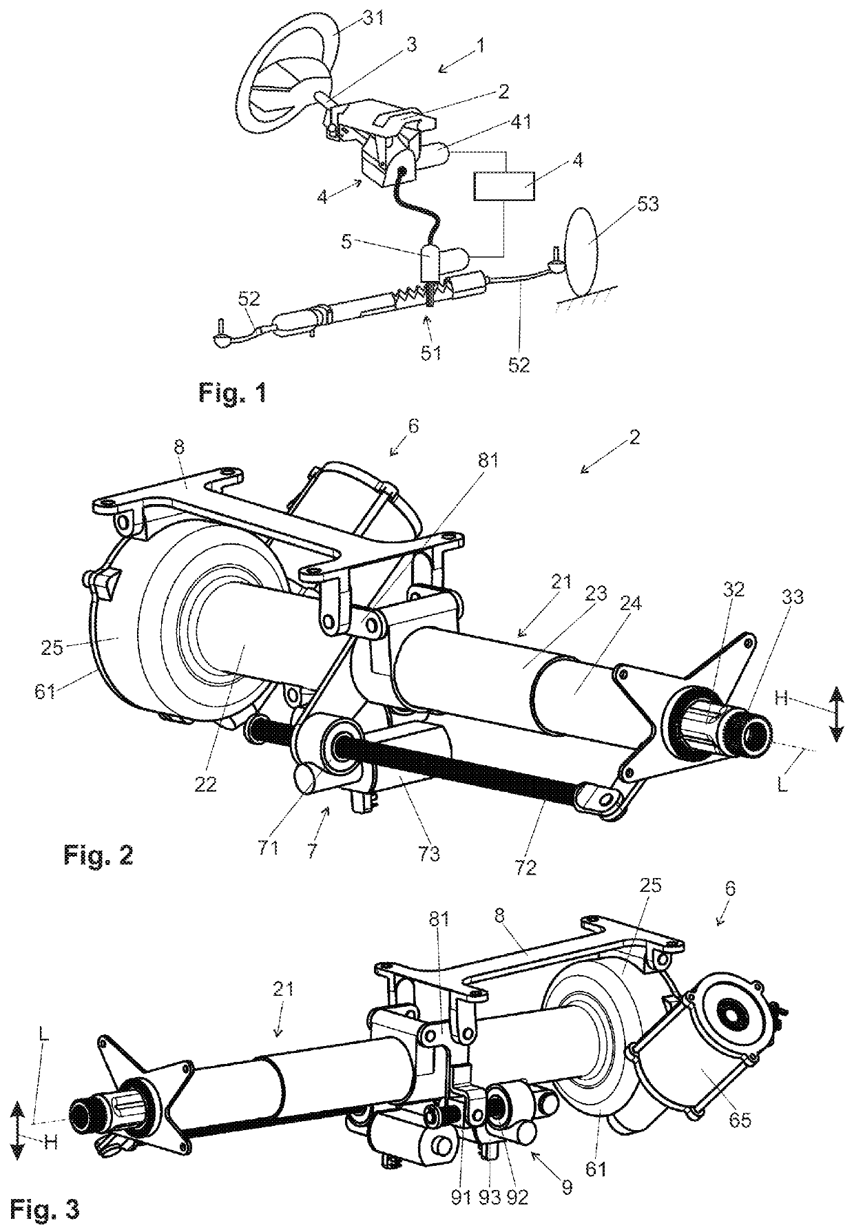
[0046]FIG. 1 shows a diagrammatic steer-by-wire steering system 1 for a motor vehicle, with a steering column 2 which can be mounted on the body (not shown) of the motor vehicle. In the steering column 2, a steering spindle 3 is mounted such that it can be rotated about its longitudinal axis L. A steering wheel 31 is fastened to the rear end (with regard to the driving direction) of the steering spindle 3, which rear end faces the driver.

[0047]A control unit 4 is connected via electric control lines to a rotary angle sensor 41 which, in the case of a steering command which is input by the driver by way of rotation of the steering wheel 31, detects a rotary angle of the steering spindle 3. The control unit 4 generates an electric control signal in a manner which is dependent on the measured rotary angle, and possibly ...


PUM


Abstract

A steering column for a steer-by-wire steering system may include a casing unit in which a steering spindle is received such that the steering spindle is rotatable about a longitudinal axis. The casing unit may have an inner casing tube, which is rotatable and longitudinally displaceable, received coaxially in an outer casing tube. The steering spindle may have a longitudinally displaceable inner shaft that is received coaxially in an outer shaft in a torque-transmitting manner. The steering spindle may be coupled to a drive unit of a feedback actuator that has an electric motor for the generation and introduction of a feedback torque into the steering spindle. The drive unit has a recess that is arranged coaxially with respect to the longitudinal axis, is open toward the outer shaft, and has a maximum inscribed internal diameter that is greater than an external diameter of the outer shaft.

Description

PRIOR ART[0001]The invention relates to a steering column for a steer-by-wire steering system for a motor vehicle, comprising a casing unit, in which a steering spindle is received such that it can be rotated about a longitudinal axis, the casing unit having an inner casing tube which is received coaxially in an outer casing tube such that it can be displaced telescopically in the direction of the longitudinal axis, and the steering spindle having an inner shaft which is received coaxially in an outer shaft in a torque-transmitting manner and such that it can be displaced telescopically in the direction of the longitudinal axis, it being possible for the steering spindle to be connected to a steering wheel, and said steering spindle being coupled to a drive unit of a feedback actuator which has an electric motor for the generation and introduction of a feedback torque into the steering spindle.[0002]Steer-by-wire steering systems for motor vehicles receive manual steering commands o...

Claims


Application Information

Patent Timeline
Patent Type & Authority Applications(United States)
IPC IPC(8): B62D5/00B62D1/181B62D1/185B62D1/19
CPCB62D5/006B62D1/195B62D1/185B62D1/181B62D1/183
Inventor FORTE, SEBASTIAN
Owner THYSSENKRUPP PRESTA AG
Learn More