
Deposition device apparatus

a technology of deposition device and apparatus, which is applied in the direction of chemical vapor deposition coating, coating, electric discharge tube, etc., can solve the problems of fracture or breakage of corroded ground straps

Pending Publication Date: 2022-03-10
SAMSUNG DISPLAY CO LTD
View PDF2 Cites 0 Cited by
  • Summary
  • Abstract
  • Description
  • Claims
  • Application Information

AI Technical Summary

Benefits of technology

The deposition apparatus described in this patent prevents corrosion and damage to the chamber caused by the cleaning process. This is achieved by using a first fixing member with a blocking part to shield the ground member, which could be corrosive if exposed to the cleaning gas. The cleaning gas passes through the blocking part and is sucked into the suction member, preventing contact with the ground member. This results in a safer and more efficient deposition process.

Problems solved by technology

However, during the cleaning process, a gas used in the cleaning process may corrode the ground strap, and the corroded ground strap may be broken or fractured.

Method used


Image

  • Deposition device apparatus
  • Deposition device apparatus
  • Deposition device apparatus

Examples


Embodiment Construction

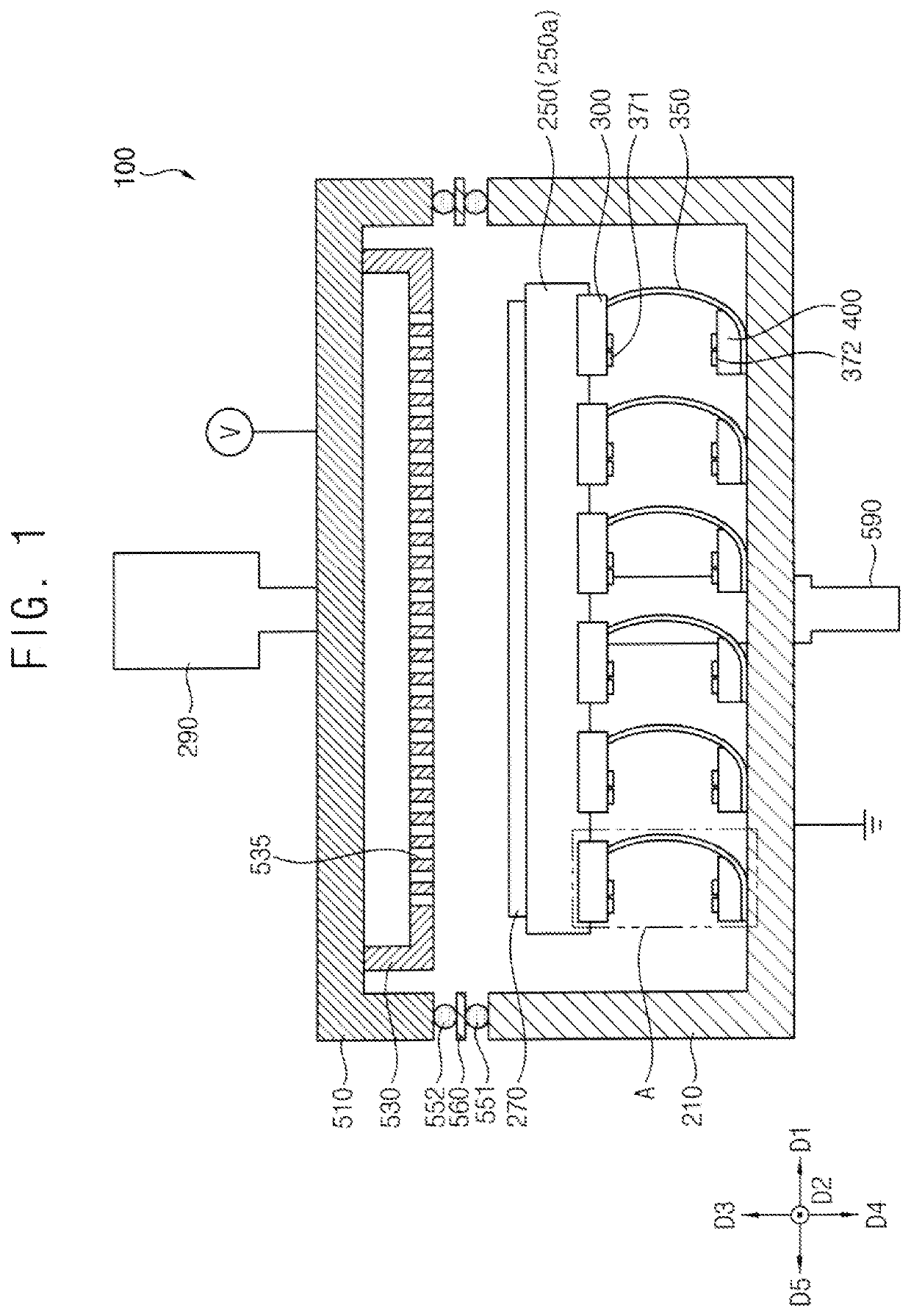
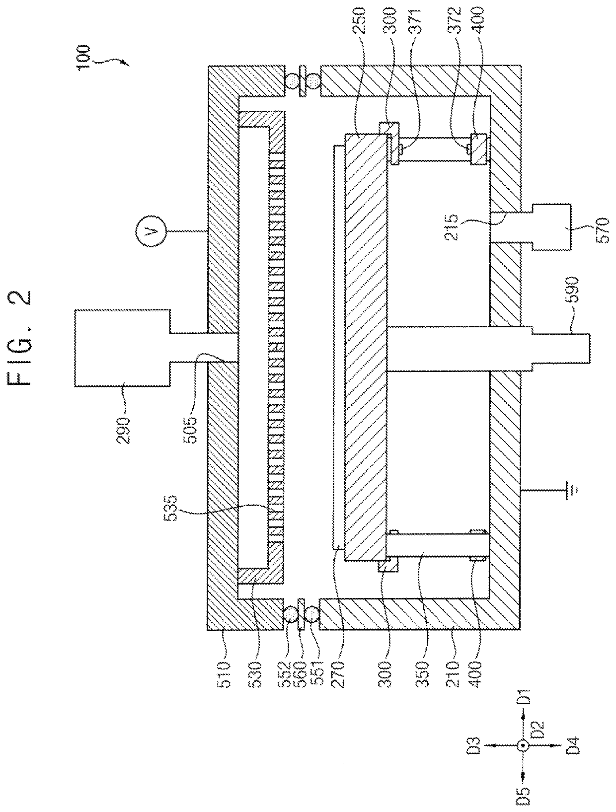
[0044]Hereinafter, deposition devices according to embodiments will be described in detail with reference to the accompanying drawings. In the accompanying drawings, same or similar reference numerals refer to the same or similar elements.

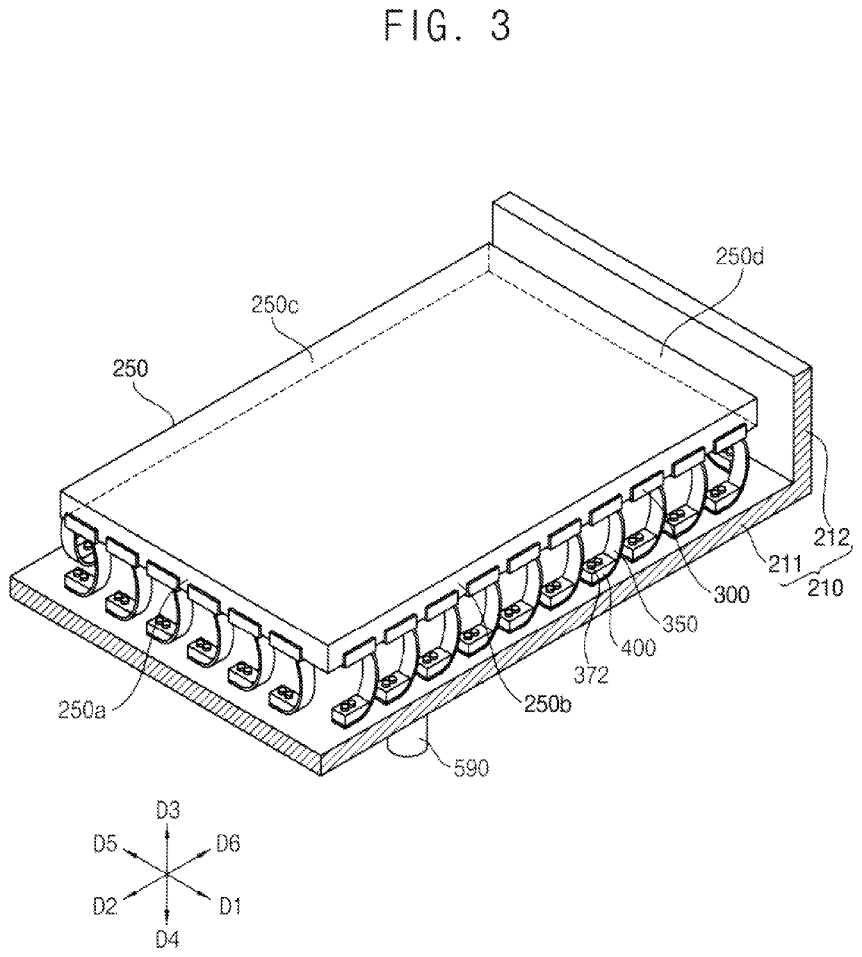
[0045]FIG. 1 is a sectional view showing a deposition device according to embodiments of the present invention, and FIG. 2 is a sectional view showing another section of the deposition device of FIG. 1. FIG. 3 is a perspective view for describing first and second fixing members and a ground member included in the deposition device of FIG. 1.

[0046]Referring to FIGS. 1, 2, and 3, a deposition device 100 may include a chamber 210, a support member 250, a first fixing member 300, a second fixing member 400, a first fixing pin 371, a second fixing pin 372, a ground member 350, a first O-ring 551, a second O-ring 552, an insulating member 560, a suction member 570, a cover member 510, a storage member 290, a distribution member 530, a lifting member 590,...


PUM

PropertyMeasurementUnit
Shapeaaaaaaaaaa

Abstract

A deposition device includes a chamber, a support member, a ground member, and a first fixing member. The chamber includes a lower portion and a side wall. The support member is located in a space defined by the lower portion and the side wall of the chamber, and includes a side surface. The ground member is disposed between the support member and the lower portion of the chamber. The first fixing member includes a first body and a first blocking part. The first body is located under a first end portion of the ground member, and includes a side surface. The first blocking part is located on the side surface of the first body and the side surface of the support member, and extends along the side surface of the support member. The first blocking part shields the first end portion of the ground member from view.

Description

CROSS-REFERENCE TO RELATED APPLICATION[0001]This application claims priority under 35 USC § 119 to Korean Patent Application No. 10-2020-0113383 filed on Sep. 4, 2020 in the Korean Intellectual Property Office (KIPO), the entire disclosure of which is incorporated herein by reference.BACKGROUND1. Field[0002]The present invention relates to a deposition device (i.e., a deposition apparatus), more particularly to, a deposition device including a ground member.2. Description of the Related Art[0003]Flat panel display devices are used as display devices for replacing a cathode ray tube display device due to lightweight and thin characteristics thereof. As representative examples of such flat panel display devices, there are a liquid crystal display device and an organic light emitting diode display device.[0004]Among methods of forming components included in such a display device, a silicon-based insulating layer, a silicon-based semiconductor layer, and the like may be formed by using ...

Claims


Application Information

Patent Timeline
IPC IPC(8): H01J37/32
CPCH01J37/32477H01J37/32715H01J37/32862C23C16/50C23C16/4583C23C16/4405C23C16/24H01J37/32577C23C16/4586C23C16/505
Inventor CHA, YOUNGSIK
Owner SAMSUNG DISPLAY CO LTD
Features
  • Generate Ideas
  • Intellectual Property
  • Life Sciences
  • Materials
  • Tech Scout
  • Unparalleled Data Quality
  • Higher Quality Content
  • 60% Fewer Hallucinations
Learn More