
Power system

a power system and power technology, applied in the field of power systems, can solve the problems of unnecessary consumption of hydrogen, and achieve the effects of preventing overcharging of batteries, and reducing the risk of overcharging

Pending Publication Date: 2022-03-17
HONDA MOTOR CO LTD
View PDF0 Cites 0 Cited by
  • Summary
  • Abstract
  • Description
  • Claims
  • Application Information

AI Technical Summary

Benefits of technology

The patent describes a control device for a fuel cell system that can selectively execute three idling stop processes based on the power system and battery state. These processes are designed to make the net output of the fuel cell system equal or less than 0, and the first process has the highest energy efficiency but the slowest recovery time. The second process has the highest energy efficiency but takes longer to resume power generation. The third process has the highest degree of deterioration but is selected as the target for idling stop when it is executed, to ensure uniform deterioration of the fuel cell systems. The control device can select the most suitable idling stop process for the power system and battery state, ensuring energy efficiency and restartability are not impaired.

Problems solved by technology

However, even under a very low load, if power generation by the fuel cell stack is continued for a long time, hydrogen may be consumed unnecessarily.

Method used


Image

  • Power system
  • Power system
  • Power system

Examples


first embodiment

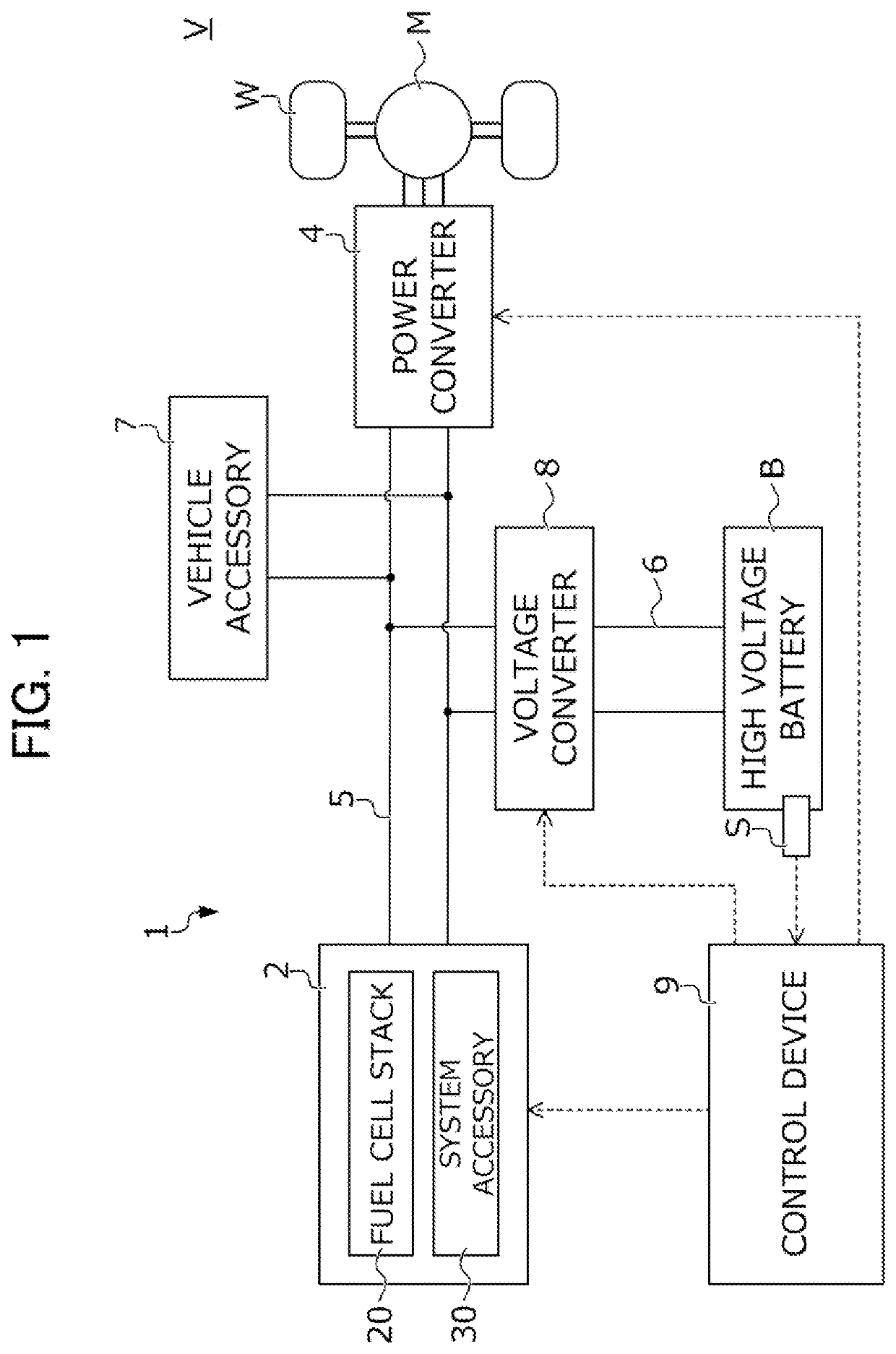
[0038]A power system according to a first embodiment of the present disclosure will be described with reference to the drawings. FIG. 1 is a diagram illustrating a configuration of a vehicle V equipped with the power system 1 according to the present embodiment.

[0039]The vehicle V includes driving wheels w and the power system 1 that allows exchange of power between a traction motor M connected to the driving wheels W, a fuel cell system 2 to be described later, and a high voltage battery B to be described later. The vehicle V is a so-called fuel cell vehicle that accelerates and decelerates using drive power produced by the traction motor M consuming electric power generated by the fuel cell system 2.

[0040]The power system 1 includes the traction motor M that causes the vehicle V to travel, a power converter A connected to the traction motor M, the fuel cell system 2 that generates power by means of a fuel cell stack 20, the high voltage battery B that stores power, a first power l...

second embodiment

[0102]Next, a power system according to a second embodiment of the present disclosure will be described with reference to the drawings. In the following description of the power system according to the second embodiment, the same components as those of the power system of the first embodiment are denoted by the same reference characters, and a detailed description of the same components will be omitted.

[0103]FIG. 7 is a diagram illustrating a configuration of a vehicle VA equipped with the power system 1A according to the present embodiment. As illustrated in FIG. 7, the power system 1A according to the present embodiment differs from the power system 1 of the first embodiment in that the power system 1A includes a plurality of (three in the example of FIG. 7) fuel cell systems 2a, 2b, and 2c and a control device 9A having a different configuration. Note that since the fuel cell systems 2a, 2b, and 2c have substantially the same specific configuration as that of the fuel cell system...


PUM

PropertyMeasurementUnit
speedaaaaaaaaaa
poweraaaaaaaaaa
consuming poweraaaaaaaaaa

Abstract

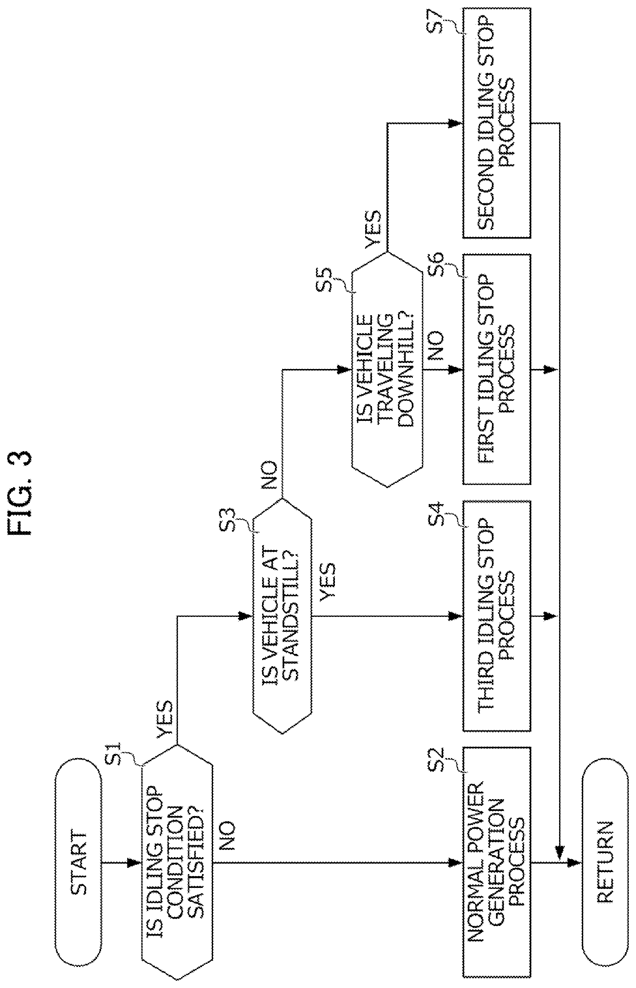
The power system includes a fuel cell stack, a system accessory, a battery, and a control device. The control device executes, based on a state of a vehicle and the battery, one of the following processes: a normal power generation process during which the control device makes a net output greater than 0; a first idling stop process during which the control device makes the net output equal to or less than 0 while continuing operation of the system accessory and power generation by the stack; a second idling stop process during which the control device makes the net output less than 0 by stopping the power generation while continuing the operation of the system accessory; and a third idling atop process during which the control device makes the net output equal to 0, by stopping both the operation of the system accessory and the power generation.

Description

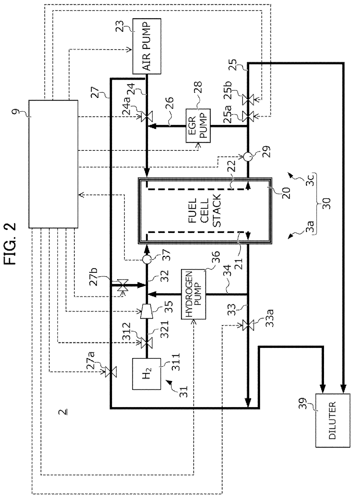
This application is based on and claims the benefit of priority from Japanese Patent Application No. 2020-152518, filed on 11 Sep. 2020, the content of which is incorporated herein by reference.BACKGROUND OF THE INVENTIONField of the Invention[0001]The present disclosure relates to a power system. More specifically, the present disclosure relates to a power system including a fuel cell system and a battery.Related Art[0002]A fuel cell vehicle is equipped with a power system including, for example, a fuel cell system for generating power by means of a fuel cell, a battery for storing power outputted from the fuel cell system, a traction motor causing the vehicle to travel by consuming power outputted from the fuel cell system and power outputted from the battery. The fuel cell system is composed of, for example, a fuel cell stack for generating power upon supply of hydrogen as a fuel gas and air as an oxidant gas, and a system accessory for supplying hydrogen and air to the fuel cell...

Claims


Application Information

Patent Timeline
Patent Type & Authority Applications(United States)
IPC IPC(8): B60L50/71H01M16/00H01M8/043H01M8/04828H01M8/04746H01M10/46H01M10/44B60L50/51
CPCB60L50/71H01M16/006H01M8/043H01M8/0494H01M8/04947H01M2250/20H01M10/46H01M10/44B60L50/51H01M2220/20H01M8/04753B60L50/75B60L58/40B60L3/0053B60L58/15B60L2240/642B60L2260/22B60L2260/26B60L58/16B60L1/00Y02E60/10Y02E60/50Y02T10/70Y02T10/72Y02T90/16Y02T90/40H01M8/04626H01M8/249
Inventor TARUYA, KENJIIGARASHI, DAISHI
Owner HONDA MOTOR CO LTD
Learn More