
Dental mill blank and dental prosthesis

a technology which is applied in the field of dental milling and dental implants, can solve the problems of difficult to reproduce the appearance of natural teeth, lack of aesthetic quality of metals, allergic reactions, etc., and achieve the effect of desirable strength and durability and easy production

Pending Publication Date: 2022-03-24
KURARAY NORITAKE DENTAL
View PDF5 Cites 0 Cited by
  • Summary
  • Abstract
  • Description
  • Claims
  • Application Information

AI Technical Summary

Benefits of technology

The present invention provides a dental mill blank and dental prosthesis with a close shade and translucency to natural teeth. The method for producing such a mill blank and dental prosthesis is easy and the strength and durability of the final product is desirable. The technical effects include improved aesthetics, ease of production, and desirable strength and durability of the dental mill blank and dental prosthesis.

Problems solved by technology

However, metals lack aesthetic quality because of the colors that are distinctively different from the color of natural teeth, and can cause allergic reaction when released from these products.
It is, however, difficult to reproduce the appearance of natural teeth (particularly, transparency and gloss (luster)) with zirconia (sintered body) alone.

Method used


Image

  • Dental mill blank and dental prosthesis
  • Dental mill blank and dental prosthesis
  • Dental mill blank and dental prosthesis

Examples


example 1

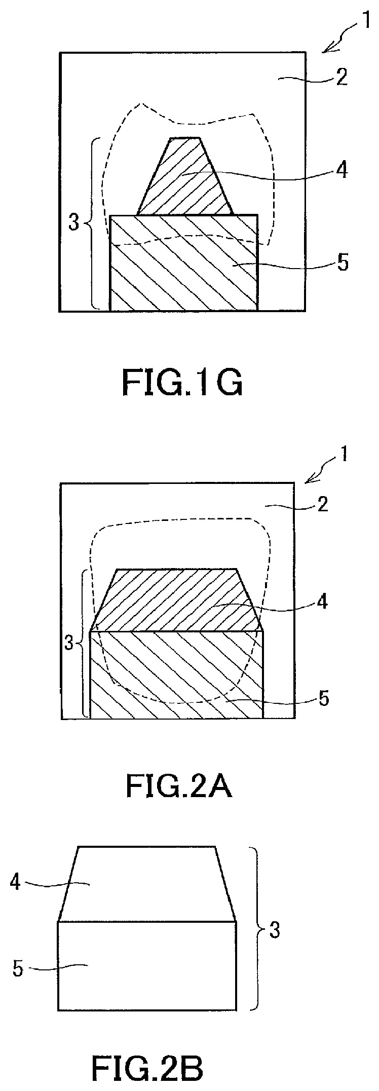
[0144]A zirconia powder was prepared that contained 6 mol % yttria as a stabilizer. The zirconia powder was filled into a cylindrical die of about 11 mm diameter with pigments in such an amount that the second portion (5) had a height of 7.25 mm after pressing. The pigments were used in the amounts shown in Table 1. For pre-forming, the zirconia powder was pressed at 3 kN, and the same amount of zirconia powder was laid on the pre-formed second portion (5) with pigments used in the same amounts. These were then pressed into a pre-formed compact. The pre-formed compact was shaved into a shape of the structure depicted in FIG. 4D as a cross section taken at the second imaginary cutting plane (7) shown in FIG. 1A. This produced a pre-formed compact of core layer (3). The pre-formed compact of core layer (3) was then placed in an 18.4 mm×20.3 mm quadrangular prism-shaped die, and the same zirconia powder used for the first portion (4) and second portion (5) was laid around the pre-forme...

example 2

[0148]A mill blank portion was fabricated, and a dental prosthesis of the present invention was obtained in the same manner as in Example 1, except that the pigments used for the fabrication of the layers were used in the amounts shown in Table 1 to provide different shades for the first portion (4) and the second portion (5).

example 3

[0149]A mill blank portion was fabricated, and a dental prosthesis of the present invention was obtained in the same manner as in Example 1, except that the pigments used for the fabrication of the layers were used in the amounts shown in Table 1 to provide different shades for the first portion (4) and the upper and lower layers of the second portion (5). For fabrication of a pre-formed compact, the zirconia powder, added with the pigments used in the amounts shown in Table 1, was pressed at 3 kN so that the lower layer (10) of the second portion (5) had a height of 4 mm after pressing, and the zirconia powder, separately added for upper layer (9) with the pigments used in the amounts shown in Table 1, was pressed at 3 kN so that the upper layer (9) of the second portion (5) had a height of 3.25 mm after pressing. The upper layer and lower layer of the second portion (5) had a shade difference ΔE of 2.3.


PUM


Abstract

A mill blank may have a multilayer structure and desirable aesthetics. Such dental mill blanks may include a mill blank portion having a layered structure of two or more layers, and in which the layered structure includes an enamel layer and a core layer, the core layer comprising a first portion that is substantially a frustum, the frustum having a side face forming a part of an interface between the enamel layer and the core layer.

Description

TECHNICAL FIELD[0001]The present invention relates to a dental mill blank and a dental prosthesis.BACKGROUND ART[0002]For years, metal has been used for a range of dental products, including, for example, prostheses (such as veneer crowns, dental caps, crowns, and post crowns), orthodontic products, and products for dental implants. However, metals lack aesthetic quality because of the colors that are distinctively different from the color of natural teeth, and can cause allergic reaction when released from these products. These issues involving the use of metal have been addressed by dental products that use ceramic materials such as aluminum oxide (alumina) and zirconium oxide (zirconia) as alternative materials of metal. Comparatively, zirconia, in particular, has desirable strength and more appealing aesthetics, and this, combined with the currently declining price of zirconia, has created a high demand for this material.[0003]For improved oral aesthetics, a dental product must ...

Claims


Application Information

Patent Timeline
Patent Type & Authority Applications(United States)
IPC IPC(8): A61C13/00A61C13/09A61C13/083
CPCA61C13/0022A61C5/70A61C13/083A61C13/09A61C13/082A61K6/16A61K6/818A61K6/822
Inventor MATSUMOTO, ATSUSHISAKAMOTO, HIROYUKIKATO, SHINICHIROITO, YOSHIHISA
Owner KURARAY NORITAKE DENTAL
Learn More