Eureka AIR delivers breakthrough ideas for toughest innovation challenges, trusted by R&D personnel around the world.

Nozzle, solid matter unloading device, solid matter unloading system, and solid matter unloading method

Pending Publication Date: 2022-03-24
NIPPON SHOKUBAI CO LTD
View PDF0 Cites 0 Cited by
  • Summary
  • Abstract
  • Description
  • Claims
  • Application Information

AI Technical Summary

Benefits of technology

The present invention provides a device that can adjust the balance between the amount of gas released to flow the solid matters and the amount of gas released to move the solid matters to the upper end opening of the device. This allows for efficient and accurate unloading of solid matters from the device. Overall, the device improves work efficiency and unloading accuracy.

Problems solved by technology

When a packing material such as a catalysts used in these catalytic reaction is used for a long period of time in a chemical plant, a catalytic function such as activity and selectivity is impaired due to poisoning, coking, sintering, or the like, a mechanical strength deteriorates, or a pressure loss increases, so that the stable and efficient operation of the plant cannot be performed.
Further, in the work place, a large amount of dust is generated so that an environment becomes poor, and thus it is inevitable for the worker to wear dustproof clothes, dust masks, goggles, gloves and the like.

Method used


Image

  • Nozzle, solid matter unloading device, solid matter unloading system, and solid matter unloading method
  • Nozzle, solid matter unloading device, solid matter unloading system, and solid matter unloading method
  • Nozzle, solid matter unloading device, solid matter unloading system, and solid matter unloading method

Examples


example 1

[0127]As the nozzle 100, nozzle number 1 shown in Table 1 was used. While the tip of the nozzle 100 connected to the conduit 200 was gradually inserted from the upper end opening portion 511 of the tubular body 510 toward the lower portion of the tubular body 510, a suction force was generated in the inside 513 of the tubular body 510 to unload all the ceramic balls filled in the inside 513 of the tubular body 510. This unloading work was carried out on a total of ten tubular bodies 510. In the work of unloading the ceramic balls from the ten tubular bodies 510, a total of 12 times of secondary blockages occurred. The average time required for unloading was 40 seconds.

examples 2 to 6

[0128]Examples 2 to 6 were the same as in Example 1 except that the types of the nozzles 100 are changed to those of nozzle numbers 2 to 6 shown in Table 1, and the unloading work was carried out on ten tubular bodies 510 filled with ceramic balls. The number of occurrences of secondary blockage which occurred during the unloading work and the average time required for unloading are shown in Table 2.

examples 7 to 10

[0129]In Examples 7 to 10, the types of the nozzles 100 were changed to those of nozzle numbers 7 to 10 shown in Table 1, and Q1 / Q2 and Q2 / Q0 were changed as shown in Table 2. Other conditions were the same as in Example 1, and the unloading work was carried out on ten tubular bodies 510 filled with ceramic balls. The number of occurrences of secondary blockage which occurred during the unloading work and the average time required for unloading are shown in Table 2.


PUM

PropertyMeasurementUnit
Angleaaaaaaaaaa
Angleaaaaaaaaaa
Forceaaaaaaaaaa

Abstract

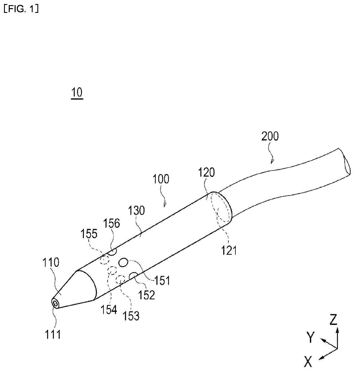
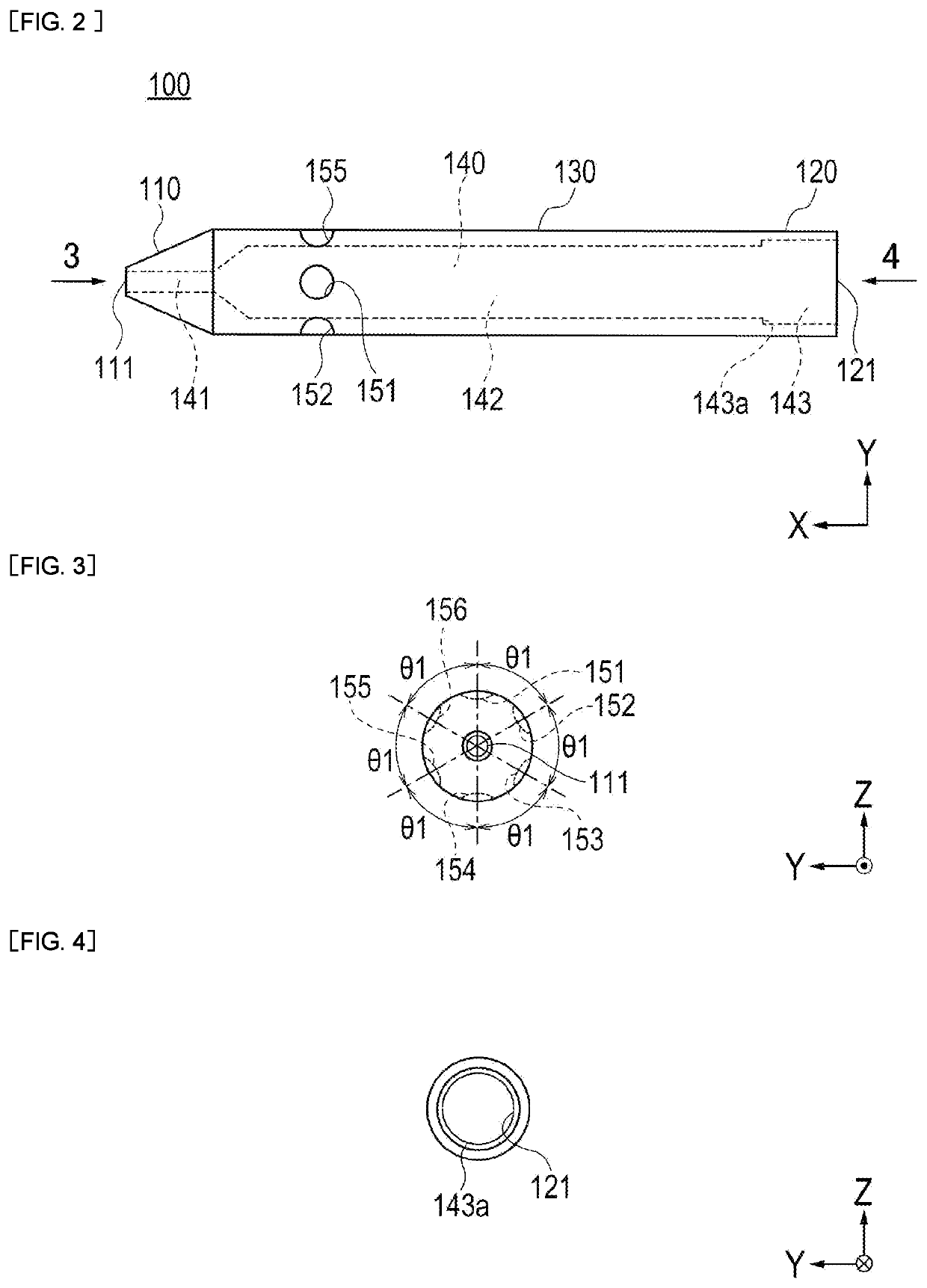
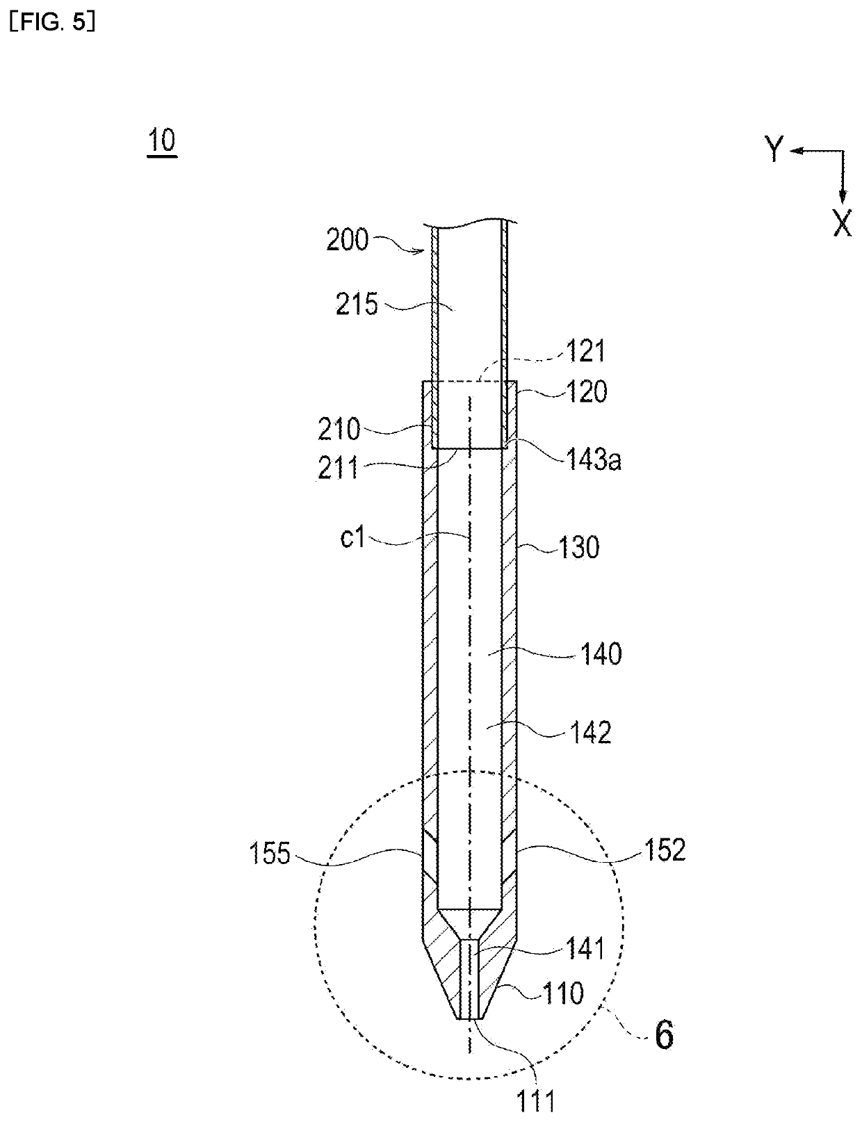
A nozzle includes: a flow path allowing gas to flow; tip opening portion(s) formed on a tip side of the flow path; a base end opening portion formed on a base end side of the flow path; and side hole(s) which is formed on the base end side from the tip opening portion and allows a part of the gas flowing through the flow path to be discharged toward the base end side. The tip opening portion(s) is formed in a direction of the flow path. The side hole(s) is formed along a circumferential direction of the flow path. When the gas is supplied from the base end opening portion, a ratio (Q1a / Q1b) of a flow rate (Q1a) of the gas discharged from the tip opening portion(s) and a flow rate (Q1b) of the gas discharged from the side hole(s) is 0.05 to 0.7.

Description

TECHNICAL FIELD[0001]The present invention relates to a nozzle used for unloading granular solid matter filled in a tubular body such as a reaction tube of a multi-tube reactor, a solid matter unloading device, a solid matter unloading system, and a solid matter unloading method.BACKGROUND ART[0002]In the field of petrochemical industry, many catalytic reaction, which uses a tubular reactor, such as decomposition reaction, reforming reaction, oxidation reaction, ammoxidation reaction, and reduction reaction of hydrocarbons are carried out. The reactors used for these reactions are equipped with thousands to ten thousands of reaction tubes (hereinafter sometimes referred to as “tubular bodies”), and the reaction tubes are filled with granular solid matters such as catalysts or inert substances suitable for each catalytic reaction (hereinafter, the granular solid matters such as catalysts filled inside the tubular body are sometimes referred to as “packing materials”). For example, in...

Claims


Application Information

Patent Timeline
IPC IPC(8): B01J4/00B05B1/00B05B1/30B01J8/06B05B1/14
CPCB01J4/002B01J4/008B05B1/005B01J2208/00761B01J8/06B05B1/14B05B1/30B01J8/004B01J2208/06B01J23/887B01J38/00
Inventor SUGIMOTO, TAKASHIGAMMA, HAJIMEYUNOKI, HIROMI
Owner NIPPON SHOKUBAI CO LTD
Why Eureka
Eureka Blog
Learn More