
System for the temporary storage of objects

a technology for temporary storage and objects, applied in the field of temporary storage of objects, can solve the problems of impairing the efficiency of the production line, forced stoppage of the upstream station, and desynchronisation of the production flow within the production, and achieve the effect of easy identification of the location

Pending Publication Date: 2022-03-24
UNIVERSITY OF SOUTHERN BRITTANY
View PDF25 Cites 0 Cited by
  • Summary
  • Abstract
  • Description
  • Claims
  • Application Information

AI Technical Summary

Benefits of technology

This patent describes a system for managing the sequencing of objects in a production flow. It uses a control unit that includes a processor and a microcontroller to detect the activation and deactivation of sensors and record the deposition of objects during the loading phase. This allows for easy management of the sequencing of objects during the production process. The system also includes a temporary-storage belt that can be easily integrated into a control system of a production line.

Problems solved by technology

Generally, asynchronisms, such as unforeseen events or breakdowns, occurring at the workstations interfere with the correct functioning of the production line by causing desynchronisation of the production flows within the production line.
This causes the forced stoppage of the upstream station.
By propagation of the phenomenon, the stoppage of a downstream station can thus cause the stoppage of the whole of the production line situated upstream, which impairs the efficiency of the production line.
An unforeseen event occurring on one of the upstream stations causes the interruption of the flow emerging from the upstream station.
This causes a wait at the assembly station, causing an accumulation of objects leaving the other upstream stations.
An unforeseen event may thus give rise to a forced stoppage of several parallel lines in the production chain.

Method used


Image

  • System for the temporary storage of objects
  • System for the temporary storage of objects
  • System for the temporary storage of objects

Examples


Embodiment Construction

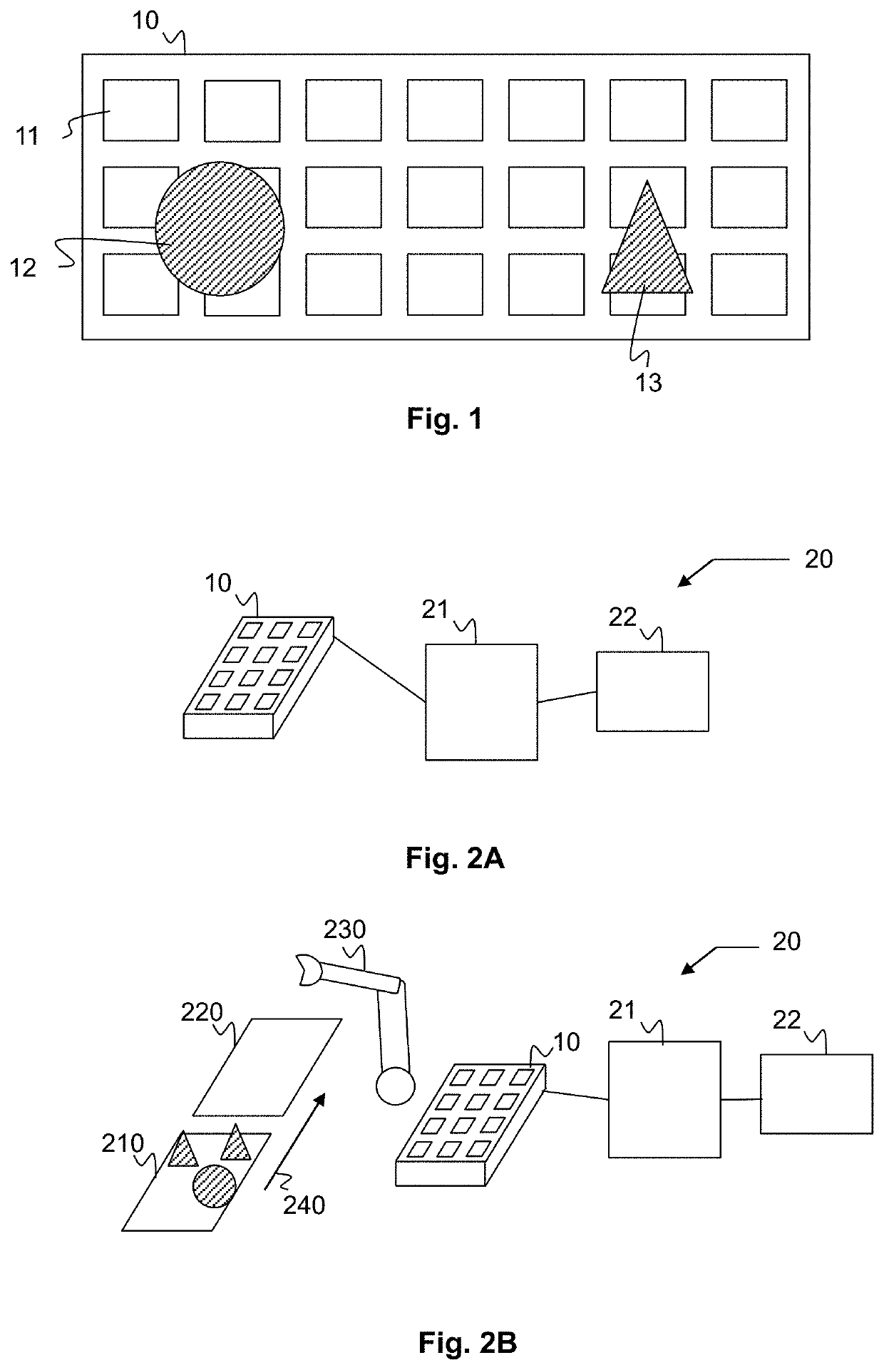
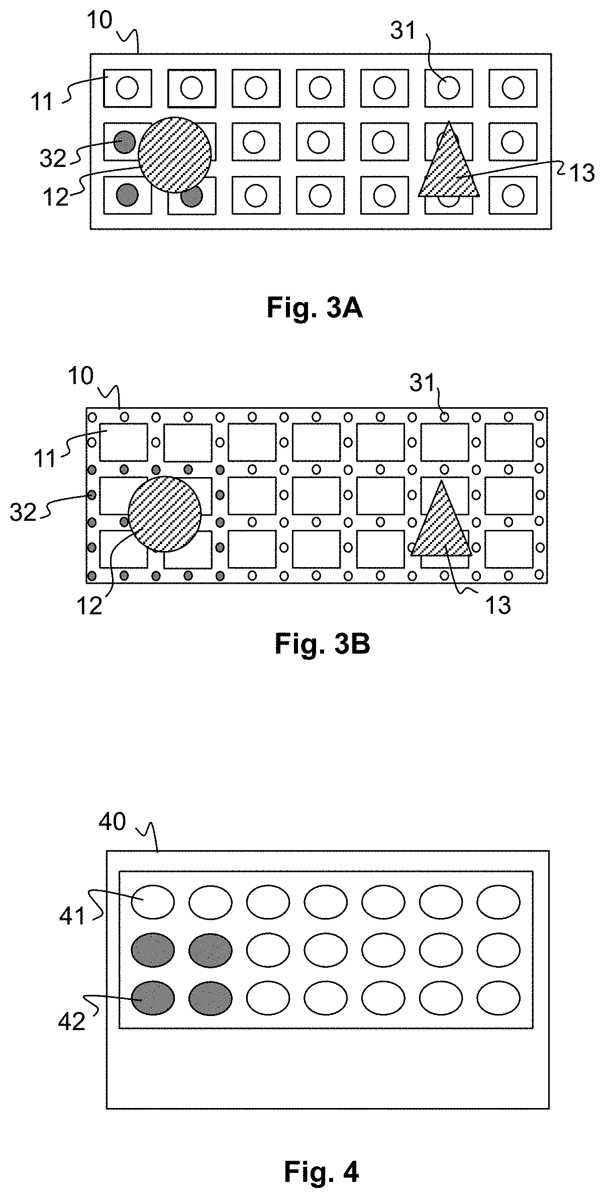
[0037]FIG. 1 shows a temporary-storage belt 10 in plan view. The temporary-storage belt 10 comprises sensors 11 integrated in the temporary-storage belt 10 and regularly distributed over the temporary-storage belt 10. The position of each sensor 11 on the temporary-storage belt 10 is distinctly identified and different from the position of each of the other sensors 11.

[0038]Objects 12, 13 can be deposited on the temporary-storage belt 10, for example by an operator or a robot. Each sensor 11 is sensitive to the presence of an object 12, 13 when said object 12, 13 is deposited in a sensitivity zone of said sensor 1. As soon as the object 12, 13 is deposited on the temporary-storage belt 10 and enters the sensitivity zone of said sensor 11, said sensor 11 is activated by the object 12, 13 the deposition of which is detected by said sensor 11. The sensor 11 is then able to transmit information representing the detection of the presence of the object 12, 13. Conversely, the sensor 11 de...


PUM


Abstract

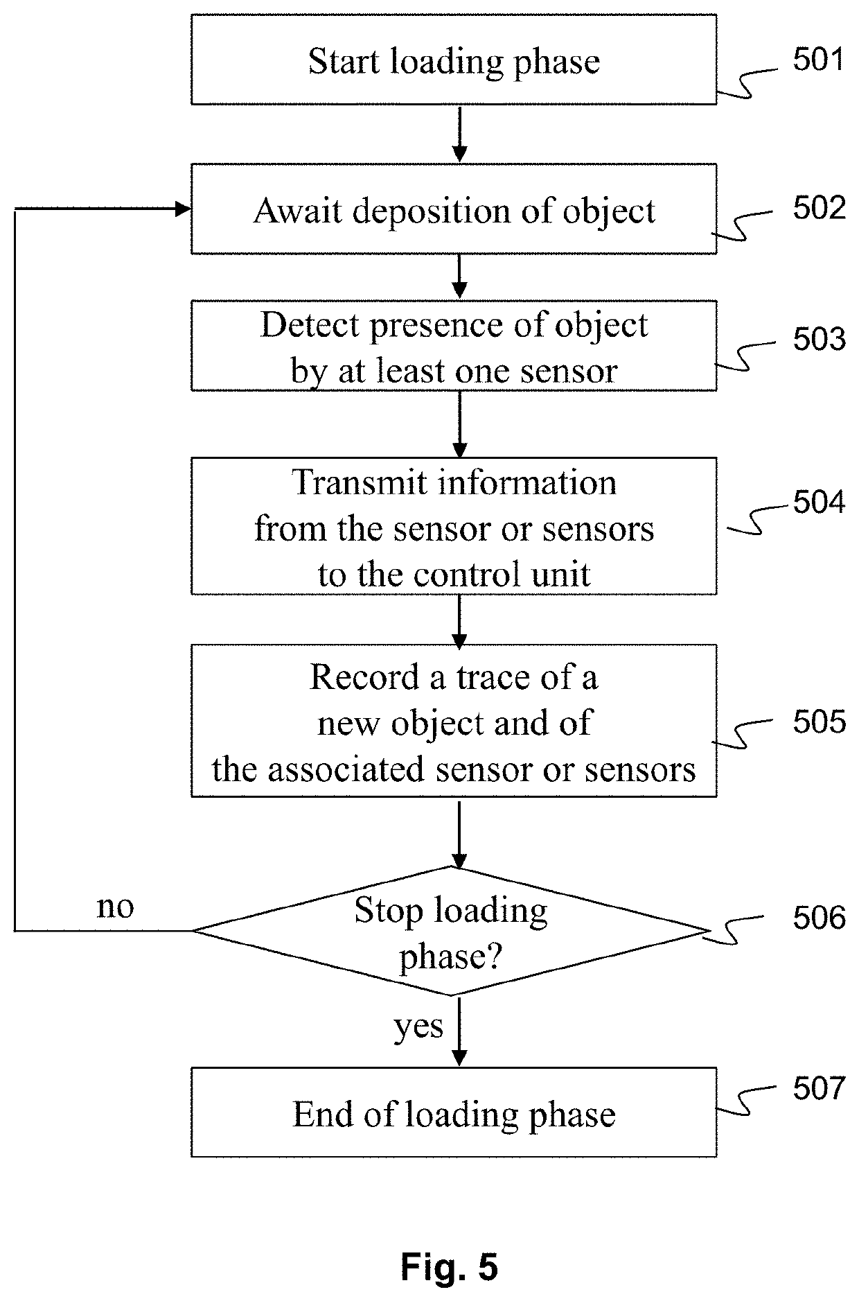
A temporary-storage system that includes a temporary-storage belt, a control unit and signalling means. The temporary-storage belt comprises a plurality of regularly distributed sensors. During a loading phase, the control unit receives information coming from at least one of the sensors when an object is deposited on the temporary-storage belt and records a trace of the deposition of the object in association with a reference to each of the sensors activated by the deposition. During an unloading phase, the control unit determines a sequence of removal of the objects and, for each object to be removed, identifies the sensors referenced, transmits to the signalling means signalling information identifying the position of the object, and receives information coming from at least one of the sensors when the object is removed.

Description

TECHNICAL FIELD[0001]The present invention relates to the field of the temporary storage of objects. One technical field of application of the present invention is arranging a production line. More precisely, the present invention proposes a temporary-storage system that is intended to be interposed between an upstream station and a downstream station of the production line, and which makes it possible to automatically manage a sequencing at the discharge, from the temporary-storage system to the downstream station, of objects previously presented to the temporary-storage system from the upstream station.PRIOR ART[0002]In a production line, the various operations of manufacturing, transforming or assembling a product are performed successively at workstations disposed in a pre-established order.[0003]In an in-line configuration where the workstations follow each other, the production flow leaving one workstation (called the “upstream station”) is directly related to the production f...

Claims


Application Information

Patent Timeline
IPC IPC(8): B25J9/16G05B19/4155
CPCB25J9/1697G05B2219/31043G05B19/4155G06Q50/04G06Q10/08G05B2219/39102G05B2219/39106G05B2219/40007G05B19/4182Y02P90/30Y02P90/02
Inventor BOMEL, PIERREMARTIN, ERIC
Owner UNIVERSITY OF SOUTHERN BRITTANY
Learn More