
Electromagnetic slosh and liquid position detection

a technology of slosh and detection, applied in the field of slosh detection and liquid position monitoring, can solve the problems of large weight penalty, inability to fully eliminate slosh force, and baffles add design and construction complexity to the tank as well as weight, so as to reduce the uncertainty of slosh force, reduce the size or weight of passive features, and improve the effect of accuracy

Pending Publication Date: 2022-03-24
EMBRY RIDDLE AERONAUTICAL UNIV
View PDF3 Cites 0 Cited by
  • Summary
  • Abstract
  • Description
  • Claims
  • Application Information

AI Technical Summary

Benefits of technology

The present inventors have identified that sloshing (which refers to the movement of a liquid in a tank or container) can cause issues in propellant tanks and other liquid systems. Current solutions involve using mechanical features like baffles to mitigate sloshing forces, but these can add weight and design complexity. Alternatively, sloshing forces can be accounted for in guidance, navigation, and control (GNC) systems like thrusters or inertial gyroscopes. However, uncertainty in modeling sloshing forces can result in larger, heavier components. The present inventors have developed an approach to actively monitor the properties of the liquid in tanks to get more accurate information and reduce the size and weight of passive features like baffle systems. This approach is non-invasive and can function in inertial or accelerated frames. Overall, the present patent addresses the need for improved monitoring and mitigation techniques for sloshing in liquid systems.

Problems solved by technology

The present inventors have recognized that generally applied mitigation techniques for sloshing can present various drawbacks, such as a large weight penalty.
Baffles, for example, are simple but cannot fully eliminate sloshing forces.
In addition, baffles add design and construction complexities to the tank as well as weight.

Method used


Image

  • Electromagnetic slosh and liquid position detection
  • Electromagnetic slosh and liquid position detection
  • Electromagnetic slosh and liquid position detection

Examples


Embodiment Construction

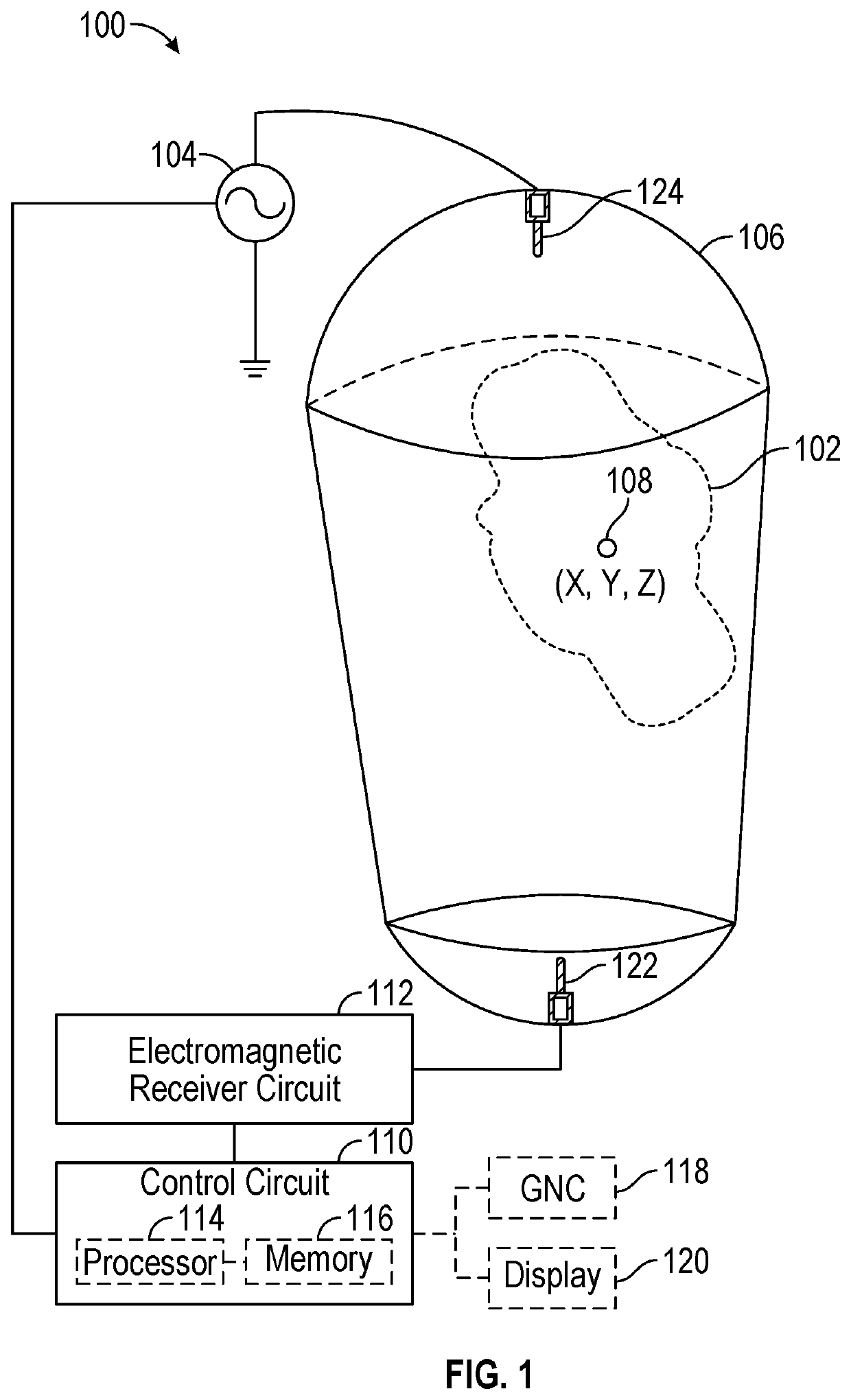
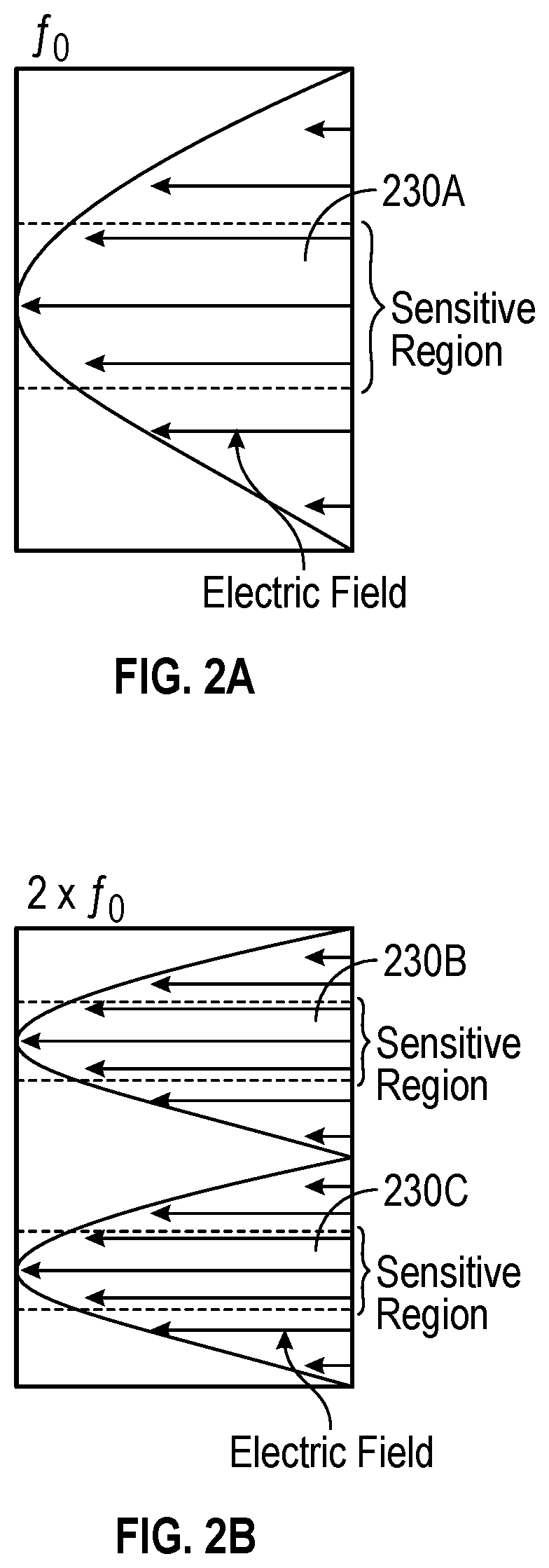
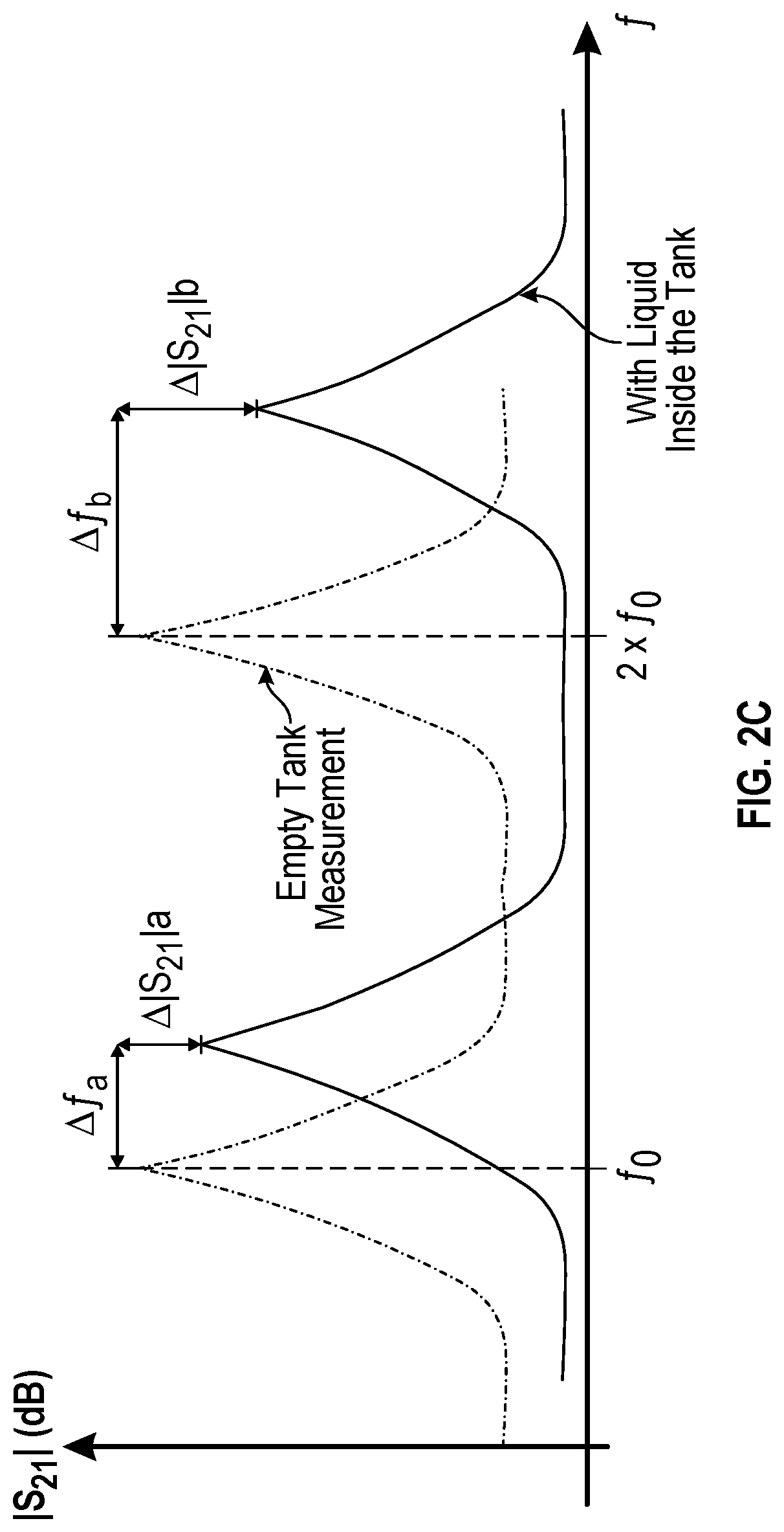
[0022]A physical characteristic such as a spatial configuration (e.g., quantity or position) of a liquid within a tank can be determined using an electromagnetic sensing approach. For example, by treating the tank as a resonating cavity, movement of the fuel inside will produce one or more of a shift in resonant frequencies (e.g., in electromagnetic resonances) or a change in quality factor (e.g., a change in damping behavior), as illustrative examples. Such effects result from differing dielectric properties air, gas, or vacuum, compared to the liquid in the tank (e.g., a liquid comprising a propellant constituent such as an oxidizer or a fuel). As shown generally below, a sphere of a dielectric medium such as distilled water can be moved linearly across a resonating cavity, and observed scattering parameters (e.g., a transmission scattering parameter, S21) also changes. Accordingly, use of a frequency domain technique can be used to determine a characteristic of a spatial configur...


PUM


Abstract

Apparatus and techniques are described for monitoring slosh of a liquid within a propellant tank. The approaches described herein can use an electromagnetic transmitter positioned at a first location on or within the tank, the electromagnetic transmitter coupled to a source of electromagnetic energy and arranged to establish a specified electromagnetic field configuration within the tank using a signal from the source, and an electromagnetic receiver positioned at a different second location on or within the tank, the electromagnetic receiver arranged to sense an electromagnetic field established within the tank by the electromagnetic transmitter. A control circuit can be coupled to the electromagnetic receiver, the control circuit configured to determine a characteristic of a spatial configuration of the liquid using the sensed electromagnetic field. The characteristic can include one or more of a position, a quantity, or a spatial distribution of the liquid, as an illustration.

Description

CLAIM OF PRIORITY[0001]This patent application claims the benefit of priority of Rojas et al., U.S. Provisional Patent Application Ser. No. 63 / 080,490, titled “RADIO-FREQUENCY BASED SLOSH AND LIQUID POSITION DETECTION,” filed on Sep. 18, 2020 (Attorney Docket No. 4568.009PRV), which is hereby incorporated by reference herein in its entirety.FIELD OF THE DISCLOSURE[0002]This document pertains generally, but not by way of limitation, to liquid position or liquid motion monitoring, and more particularly to electromagnetic-based liquid position or liquid motion monitoring, such as for slosh and liquid position detection in propellant tanks.BACKGROUND[0003]Vehicles with liquid-filled tanks can be subject to inertial sloshing forces induced by vehicle motion. Mechanical interaction occurs when there is relative movement between a vessel and a liquid contained therein. This liquid-vessel interaction, which is known as an inertial wave, affects the overall dynamic behavior of the vessel, su...

Claims


Application Information

Patent Timeline
IPC IPC(8): G01P15/125G01F23/26
CPCG01P15/125G01F23/263G01F23/284G01S13/88G01F22/00G01F23/80
Inventor ROJAS, EDUARDO ANTONIOUDREA, BOGDANSOMMER, DANIELMOLINE, NICHOLAS
Owner EMBRY RIDDLE AERONAUTICAL UNIV
Learn More