Freezing of biological material
- Summary
- Abstract
- Description
- Claims
- Application Information
AI Technical Summary
Benefits of technology
Problems solved by technology
Method used
Image

Examples
example 1
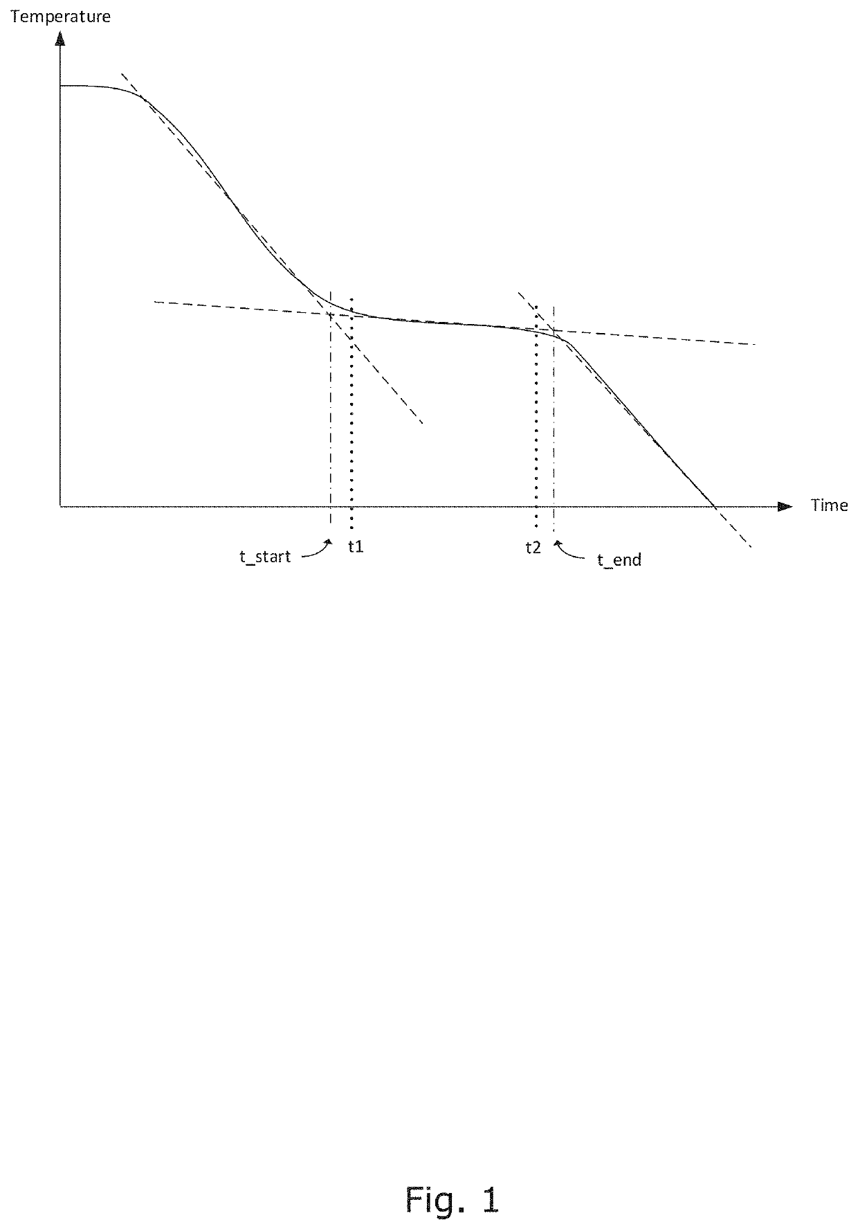
[0213]Example 1 shows the effect of changes in the duration of ice-formation time for cryopreservation of human cells of the two established cancer cell lines T-47D and T98G in presence or absence of 5% DMSO and in presence or absence of overlapping static magnetic—pulsing electric fields.
[0214]The objective was to test the importance of the duration of ice-formation time (=time to remove latent heat during ice formation) of seed stocks of two established human cells lines: T-47D breast cancer cells and T98G glioblastoma cells, for viability after thawing. In addition to variation in ice-forming time two variables have been tested:[0215]Cells frozen without DMSO or with 5% DMSO[0216]Cells frozen within a mixed strong magnetic (0.2-0.3 T)-pulsing electric (20V (220V / m)-20kHZ) field (hereinafter termed “Strong MAG / PEF”), or just outside the Field Box in a weak magnetic (0,005-0,008T)-pulsing electric (7-16V (75-185V / m)-20 kHz) (hereinafter “Weak MAG / PEF) field.
[0217]The experiment aim...
example 2
[0226]Example 2 shows the effect of changes in the duration of ice-formation time for cryopreservation of adherent CHO cells in presence or absence of 5% DMSO and in presence or absence of overlapping static magnetic—pulsing electric fields.
[0227]The objective was to test the importance of the duration of ice-formation (=time to remove latent heat during ice formation) of seed stocks of adherent CHO cells (chinese hamster ovary cells K1 for viability after thawing. In addition to variation in ice-forming time two variables have been tested:[0228]Cells frozen without DMSO or with 5% DMSO[0229]Cells frozen within a mixed strong magnetic (0,2-0,3T)-pulsing electric (20V (220V / m)-20kHZ) field (hereinafter termed “Strong MAG / PEF”), or just outside the Field Box in a weak magnetic (0,005-0,008T)-pulsing electric (7-16V (75-185V / m)-20 kHz) (hereinafter “Weak MAG / PEF) field.
[0230]The experiment aimed to determine the influence of reduced ice-formation times down to 2 min and in addition det...
example 4
[0248]The objective was to test lysis of erythrocytes after freezing with short latent heat removal time and thawing.
[0249]Eight blood samples of 3.5 mL each where drawn from a healthy, non-medicated male individual into Vacuette K2EDTA tubes. Two tubes where stored at +20° C. and used for control. The other tubes where positioned adjacent to tubes containing 0.9% NaCl in the freezing apparatus. The tubes containing 0.9% NaCl were equipped with temperature sensors allowing to measure the process of removal of latent heat from the liquid. It is assumed that the removal of latent heat from the 0.9% NaCl-solutions is identical or close to identical to the removal of latent heat from the close standing blood samples. Two blood samples were allowed to freeze in a process where latent heat from ice-formation was removed over a time interval of 2 min. Two other samples were allowed to freeze in a process where latent heat from ice-formation was removed over a time interval of 2 min. 29 sec...
PUM
 Abstract
Description
Claims
Application Information
 - Generate Ideas
- Intellectual Property
- Life Sciences
- Materials
- Tech Scout
- Unparalleled Data Quality
- Higher Quality Content
- 60% Fewer Hallucinations
Browse by: Latest US Patents, China's latest patents, Technical Efficacy Thesaurus, Application Domain, Technology Topic, Popular Technical Reports.
© 2025 PatSnap. All rights reserved.Legal|Privacy policy|Modern Slavery Act Transparency Statement|Sitemap|About US| Contact US: help@patsnap.com